 Vol. 2 CONTENTS
5. the process of drawing
5-1. Steps of the process
Vol. 2 CONTENTS
5. the process of drawing
5-1. Steps of the process
Step 1. Draw two center lines
Step 2. Determine the framing
Step 3. Confirm the framing much more exactly
Step 4. What is the Horizontal line? and What is the Vertical line?
Step 4-1. about Vertical line
Step 4-2. for the Flog Perspective
Step 4-3. Why do I mention about the Horizontal line and Vertical line?
Step 4-4. the additional explanation about Horizon and a vertical line
Step 5. Confirm your eye position
Step 6. Determine the whole lay-out
Step 6-1-01. You need to understand the desposition of the object
Step 6-2. Measuring each object, not geometrical object,tree, mountain
Step 6-3. Checking out each relative positions and proceeding measuring

Step 6-1-01. You need to understand the desposition of the object for
Step 6-1-02. Measure the targets on each layer
Step 6-1-03. another examples about measuring
Step 6-1-04. another examples for measuring
Step 6-1-05. about our limitation of accuracy
Step 6-2-01. measuring about a tree on layer 1=near distance
Step 6-3-01. It is quite important that we are always checking out
Step 7. Observe the objects with binoculars and determine the figure
Step 7-1. Finish the layer 3=far distance part
Step 7-1-01. How to draw layer 3=far distance, smaller details?
Step 8. Finish the layer 2=middle distance
Step 8-1. How to draw layer 2?

5
 he process of drawing
The process of drawing will be different for each case. And the process
is just a summary and common procedure, so you can't finish your drawing
only to trace the process, you need to examine the structure of your view
and understand the relative positions and nature of what you are going
to measure.
But you have to have above all sympathy with the trifle things and the
ordinary scenes of daily life and the nature itseleves. Because to draw
examiningly each object one by one to fill each up small part, needs paintience
for long time work, and seems to be often very monotonous process without
the ability to enjoy to find out even a trifle thing.
You can say easily or for just by a mouth without the sympathy like a saying "the world that I see is beautiful!", but you can't do it. You can't fill up even a bit, if you think a beauty is only in an idealism like a Raphael's painting or a scene of ancient Greek.
For my drawing scale was invented for dipicting
exactly those details of daily life and the
process that I am going to explane is just
to do that.
What you can get by my drawing scale is only
a exact lay-out of the view that hasn't details
and contents, just lines and skeleton. Just
your volition's that fill up the details
and contents.
If you want to try by yourself this method, even though you haven't experienced
about long time sketching on the field, then you had better to choose smaller
sheet size, for instance, 260x130mm. The length "l" of the drawing
scale can't be longer beyond you arm. (fig 3) If the length is same l=600mm
as the instance (fig 16), then the effect of barrel shape becomes bigger
according to the distance from the center to the peripheral, so the effect
becomes smaller for a small sheet size.
I need 50 to 90 hours to finish for a sheet
size, 260x520mm or 330x510mm.
The sheet size 130x260mm is 1/4 area of the
size, 260x520mm. So roughly saying, I may
be able to finish the smaller size for 13
to 23 hours or much more quickly.
If you had had enough experience, then you can do much more longer work
that needs patience. But you will be lost your way on too long way beyond
your expectation without a map as a experice, you won't be able to understand
only what you are going to do at first time.
So you have to choose smaller size, if you want to try it only by your curiosity. Still you won't be able to do it , if you can't draw or paint even a simpler subject.
We can't advance but one step by one, especially for those that needs technique.
But I proceed to explain the process for
the sheet size 260x520mm.

5-1
 teps of the process
Step 1.
Draw two center lines.
This step isn't necessary, but I do it like
a mechanical drawing for temporary use.
I draw two center lines exactly on center
to the height and width of the sheet.
And I used to draw border lines surrounding the image size on the whole
sheet of paper.
Landscape in Osaka: sheet size; 370x550mm,
image size; 260x520mm
Landscape in Otsu: sheet size; 370x550mm,
image size; 280x510mm/330x510mm
I have two reasons.
One is, it looks better for a drawing or watercolor to have blank margin.
The other is, I can scribe data, memo and signature or other scribles.
I don't like sign directly on the part of my image especially for landscape,
because I draw precisely details, if I signed directly on the image, then
my signature had hidden or damaged my details. My drawing or watercolor
is itself my signature, so truely I think I don't need to sign, but there
are many people who trust on much more a mere name by written letters than
a work itself.
But like a still-life fish itself having much more blank margin with calligraphic
letters is very effective and impressive by the combination the image and
letters.
Step 2.
Determine the framing.
By my method, you can't contain the objects as you will. On this point,
the method is the same as a camera by the view finder.
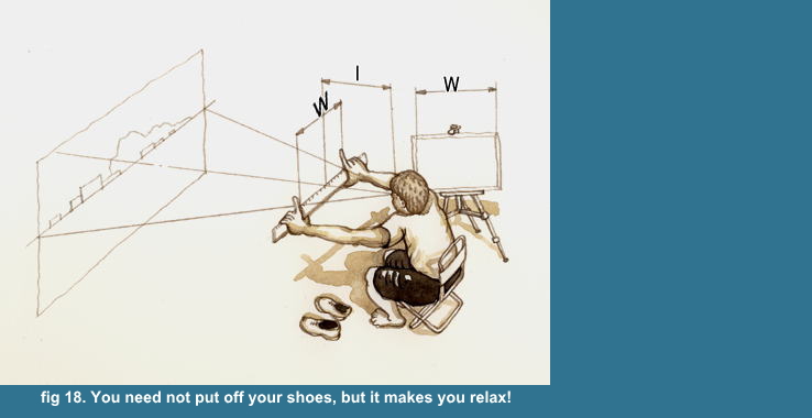
So you need to confirm roughly your framing of picture, which objects can
be contained in your framing. As my drawing scale is matched the "l"
to my reach (fig 3), so I can confirm roughly the framing by a scale 600mm,
stretching my arm and comparing the sight with the scale of span W=520mm
for the width and 260mm for height.
What I can draw on my sheet 260x520mm is roughly in the scale between zero
and 520mm for widh, zero and 260mm for height. (fig 18)

Step 3
 onfirm the framing much more exactly
Then you need to confirm the framing much more exactly. Because the particular
objects on both side ends are often to give the important role or impression
to the composition, so you need to cofirm exactly whether the objects will
be contained or not.
And you need to remember, that the line a'b' is smaller than the segment
a'b' (fig 4), and the line is the value by the above mentioned roughly
measuring by hand, and the segment is the value by the measring by my drawing
scale. So I won't be able to contain the important object on an end or
both ends, unless I hadn't confirm exactly the framing.
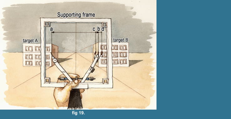
From the end of right hand or the left or even the center, I measure
by a dividers the distance between two objects (target A and B, fig 19) recognized clearly
as a mark in the middle distance for depth, and each measured value (the distance ab) is better less than 50 to 100mm.
I can measure the value 160mm as the maximum value.
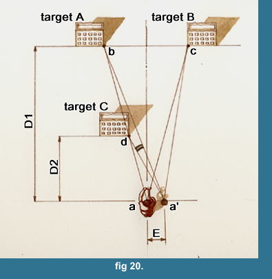
 And this is very important for measuring, that you must never measure the distance between the objects on too much different distance (D1 and D2)
for depth(target B and C, fig 20), becasue those may give often different value by the error of your eye position "E", and I can say it for the objects on near as well.
And this is very important for measuring, that you must never measure the distance between the objects on too much different distance (D1 and D2)
for depth(target B and C, fig 20), becasue those may give often different value by the error of your eye position "E", and I can say it for the objects on near as well.
You can easily make it certain that fact, by changing your eye position
to 'a' side, if the distance or the relative positon between the objects
will be changed or looked different, then you must look out and measure
another unchangeable or neglectable value between objects.
Of course, you can get the same value by measuring "bc" and also
"dc", because point "b" and "d" are on the
same line "ab",
unless your eye position "a" have changed. (fig 20)
You know by the former examination(4-3-03-03, 4-3-03-04) that the value
"bc" remains almost same for the error of eye position "E".
But the value "dc" will be changed from "dac" to "da'c"
by the error "E". The value of differece "da'b" will
become much bigger value by the ration D1/D2.
So you must never measure the target B and C, but A and B.
The former examination(4-3-03-05) can be applied for this case.
Still you may measure the distance "dc" when the ratio D1/D2
is nearly D1/D2=1 or target B, C are in far distant.
The point of the question is whether the angle "dac" and "da'c"
are almost same by the error "E" or not.
lastly for Step 3, if you can't contain the
objects as you will, then you need to walk
around and find out another position with
your tool until you are satisfied your compostion.

Step 4
 hat is the Horizontal line? and What is the Vertical line?
There are only two straight lines as the imge of straight line in our view
field, as I mentioned about (4-3-05) (fig 15). The other straight lines
appear as approximately straight, or we aren't aware of its being curved.
Horizontal line:
I say it strictly, precisely, exactly, the
Horizontal line will be looked out for the
tangential direction on your eye position.
And the earth is globe, then it is probably
far in the universe.
But I am very generous man. I think I may
say that if you can see Horizon, then it
is approximately the Horizontal line that
we seek.
If you can't find out Horizon, then what
should you do?
You have to look out the
substitution for Horizon by a binoculars.
See fig 21, you can see the roof and left side wall of building A. Then the roof of building A is below your eye position, i.e. Horizontal line.
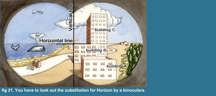
You can't see the roof of building C, but
the left side wall,and the top edge of the
left side is converging to the center. Then
you can understand that the roof of building
C is above your eye position, Horizontal
line.
So you can judge whether a line is Horizontal
line or not, by the view of a roof and side
wall.
If the roof of a building can't be seen, and the top edge of the side wall
isn't converging along the depth, i.e. the top edge of the side wall and
front wall are on the same level line, then its are on Horizon, i.e. Horizontal
line.
Be caful of the judgement! The top edge of
building B is also on Horizon, because we
can judge it by comparing Horizon. If there
isn't seen Horizon, you can't judge whether
the edge is on Horizon or not. Because the
side wall of building B isn't seen. You can
see another building behind building B on
center. Any side wall of the building also
isn't seen about the building. So you have
to examine the converging side by Perspective.
If the top edge of the converging side is
on level, then the edge is on Horizon on
the center of your view fild.
When you can't see Horizon, then you have to find the substitution, the
building
at enough distance by your binoculars by above mentioned method. For the angle between Horizon
and the building's roof at enough distance will be nearly unchangable by
our eyes angle.

Step 4-1
 bout Vertical line
I think I need to be explain about Vertical line. What I say as Vertical line is the Vertical line on the center of a view field. Indeed I say it again, the others are looked as curved on our image.
But,
as far as we turn our head, or our eyes to the object that we are going
to measure, the the object will be set on the center of our visual field. So all
the objects that face to the direction of the nomal line on the cernter
of our eye, will be seen as a straight vertical line.
And we can't measure the object without turning our head or eyes. So it
is impossible to find the only virtical line as the case of Horizon.
So I declare that the Vertical line is on the center of picture. But this
declaration isn't important, but just formal. Because I deal with all the
vertical lines as straight vertical line, and it will be natural for a
painting, I think.
And this process is only to confirm which building or object is on the
center, or near it.
By the same way with Horizontal line, you
can make it certain whether the line is on
Vertical line or not.
For this case, you need to find out the converging side, the roof of a
building. If one of the edge is on the same perpendicular line of the front
wall, then it is Vertical line.
These explanations about Horizontal and Vertical line are, of course, assuming
the Bird's eye Perspective, view from a hill or higher eye position. So
I can judge those by the shape of roof.
Step 4-2. for the Flog Perspective
What should we do for the Flog perspective, low eye position on flat ground?
Then we can't see that important view, the shape of roof.
Honestly, I seldom have the Flog Perspective.
Becasue only the near objects compose the
whole view and hide completely behind its,
don't make me feel the extention of space.
And the composition is rather simple.
If there isn't the object like for Bird's eye Perspective,I have to find out the Virtical line for
the mark on ground,
or
the row of roof tiles on slant roof, or
the details of windows, or
the scattered object on a Perpendicular line.
And when there is nothing, you can set the Vertical line on the center
line of the picture, very simple!.

Step 4-3
hy do I mention about the Horizontal line and Vertical line?
I have to do so to avoid the misunderstanding about the view field.
The
exactly straight Horizontal and Vertical line as our image on retina is only one for each,
I think I may say again. And that is on the center of our eye's view field,
so Horizon will be also seen as curved line for our eye's angle. You can
see well that effect by the wide-angle lens of a camera for high or low
angle shot.
So the image of only one straight Horizontal or Vertical line are chaninging
according to two center line of view field being chaninged by the view
angle, our head or our eyes angle.
So the
straight Horizontal and
straight Vertical line that I have explained are truely or simply two center line
of the picture. But I think we can't accept a curved Horizon as Horizon
except an unusual or a fantastic image. Then I declare that Horizon is
a straight Horizontal line anywhere in the picture. This declaration is
important especially for Horizon. For the Horizon is a important base line
of a landscape for measuring. And I think the straigh Horizon must be the
natural image for our psyhcological existing. And the other horizontal
lines measured from the Horizon naturally gather up the barrel shape. Almost
all Vertical lines can be deal with as a straight perpendicular line, unless
the effect of perspective is needed, must be the natural image, I think.
But if you use a sheet in long side for height,
then the Vertical line will be a base line
on the contrary of the former explanation
On this Step 4, three points are important.
Those are below.
1. Horizon is always drawn as a straight
line, wherever Horizon will be arbitrarily
placed on a sheet.
2. Vertical line is usually drawn as a straight
line, unless the effect of perspective is
needed.
3. We can make it certain whether any line
is on the Horizontal or Vertical line or
not by examining the edge of each converging
side.

Step 4-4
he additional explanation about Horizon and a vertical line
We know that our landscape is the thin layer spread on the surface of the earth, no more than serveral handreds meters,
except the mountains. I suppose that those
daily understanding about our environment will affect our psychological recognitions.
However the earth is a globe, our usual sight will appear as exactly the
flat land expansion as far as we see it on the earth, even the Horizon of the Ocean will be the same for our psychological recognition, though I haven't really see it once, for we had no true straight line independent from our eyesight as a standard, we had no certification
for our sensation, but just we believed it, all the straight objects must be curved within
our eyesight image.
So all the buildings stand perpendicularly on that flat land expansion might be expected to appear as the straight vertical line is psychologically the natural recognition
as a picture.
Why do I repeat to mention that?
For , as I have mentioned, the image by the measuring by my drawing scale
is shaped as the barrel image as spherical coordinates. ( fig 15 ) That
means that all the horizontal lines and vertical lines except the two center
line equally lean toward the two center lines.
However the picture is exact for the result of a measuring, we might never
be able to willingly accept the clearly perceptible slant buildings and
houses on the peripheral of a picture.
We can't control it for a photo, ( indeed a camera gives us a picture only
to push the release, but once we pushed it, then the camera had finished
its job indifferently about our interesting) but a picture, a drawing,
for we have ourselves to draw it all.
So we might naturally ask much more the natural image for our recognition.
And it's much more easy to draw by treating every vertical line as a straigh
vertical line.
Here, I give priority to the psychologically natural image as picture much
more than the exactness of measuring.
Those declaration about Horizon and the vertical lines has to be understood
on that meaning.
So there happen, especially on the peripheral, the disagreement between
the measurement and the drawing, and that is caused by the different principle
between the measuring by spherical coordinates and the actural process
by the psychological recognition.
But I believe it is reasonable way.

Step 5
onfirm your eye position
We have confirmed the Horizontal and Vertical center line on Step 4. So
we know now which object is on the Vertical center line.
Then we have to recognize where the position of our eye is.
Because when we measure the relative distance between objects on different
distance along the depth, then we have to set our eye exactly on the center
position, especially it is important for Horizontal center position. For
our head position is always changing while we are drawing, unless we fix
our head on something post. Though we know by the examination (4-3-2) that
we need not to fix our head, when we measure each object or the distance
between object on the same distance along the depth.
And we can't finish the landscape in a day,
we have to work at least 10 days , 50 hours.
So we have to confirm our position and exact
eye position.
We can confirm our eye position easily by checking the relative position
target A and target C, its alignment. (fig 20)
I have mentioned that the relative position is easily changed by the error of eye position. So we can check our eye position by that.
It is needless to say that the targets need not be always the building's
edge. We can choice other objects or details, post, window, etc as well.
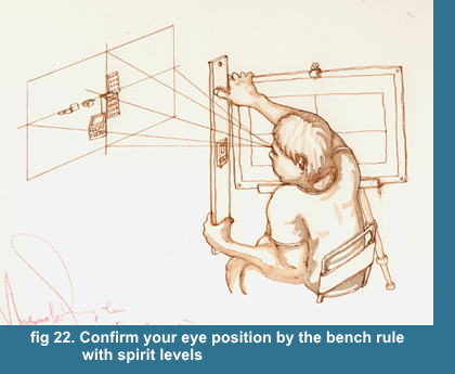
I use the bench rule with spirit levels,
that I glued an acrylic spirit levels on
an transparent acrylic rule. So I can confirm
Horizontal level and Vertical line by the
rule.(fig 22)

Step 6
 etermine the whole lay-out.
Step 6-1. Measuring each structures in middle distance, then near, then far from
center to peripheral.
Step 6-2. Measuring each object, not geometrical object, tree, mountain,
river, etc by its characteristic points.
Of course, these lay-out are drawn by pencil
for just out line, temporary line.
And the structures in far distance are usually very small in picture plain, about less than 10mm.
So I don't draw it precisely and measure except the important object, and
leave them as blank. You have to examine and draw them with binoculars
by eye measurement. You will confirm the same thing again, when you draw
it with pen and for coloring, even if you drew its precisely with pencil,
unless you left the pencil line as a line for finish.
Because you will probably forget what you have drawn, for its are too small
and meaning less drawing as independant objects except the role to fill
up the blank by its atomospher, just atomospher supporting the whole perspective
effect.
And you need to understand what it is that you are going to draw, especially
when you are to draw the determined line, unable to correct again. So I
usually draw those very small details directly by pen as decisive conture
line and coloring.
Step 6-3. Checking out each relative positions and proceeding measuring
As the lay-out proceeding to the finish, one object is to have many relative distance between the other objects, so you have to check its whether the relative position is correct or not.
What should you do, if the lay-out wasn't correct?
You had better to correct it, if the measuring has been just starting,
or if it is the fatal error for you.
But you need not correct it and should compromise, if the measuring is almost finishing thruough the much troublesome working. No one will be aware of your mistake, if you don't say it.
No one can be, even if you said it.
This is a picture.
But if you don't like it, then you can correct it as well.

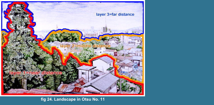
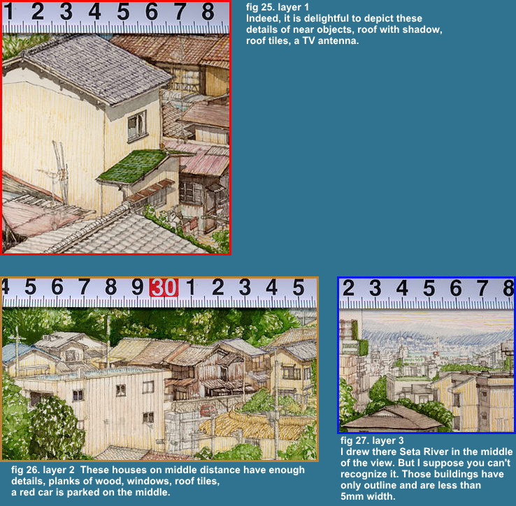
tep 6-1-01
 ou need to understand the desposition of the object for a
separated each layer as the row of the objects along the depth. (fig 23, 24, 25, 26, 27)
ou need to understand the desposition of the object for a
separated each layer as the row of the objects along the depth. (fig 23, 24, 25, 26, 27)
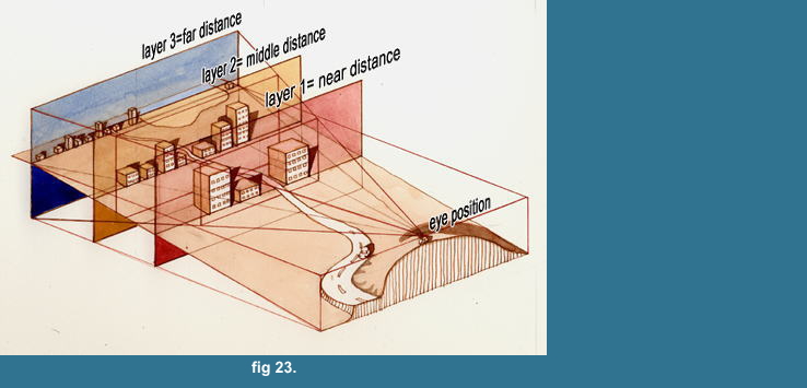
Each layer has depth as a zone, though I
show each layer as a plain for just explaining
on fig 23.
layer 1=near distance:
The value of measurement or the image or the relative position of the objcets
on this layer 1 are easily chaged by eye position. Namely, Those are comparatively
too near for the error of eye position to neglect it, I may say it less
than 50m from eye position, as I have examined on 4-3-03.
Those have rich details and will give the most impressive part to the picture.
( fig 24, 25 )
layer 2=middle distance:
The valuse or the image or the relative position of the object on this layer 2 are hardly changed by the eye positon. Namely, those are enough far to neglect the infleuence by the error of eye postion,
I may say it much more than 50m from eye position.
Those objects have also enough details and concrete images deserved to
depict, and may give the impression of extent as space. ( fig 24, 26 )
layer 3=far distance:
The objects on this layer 3 aren't changed
by the error of eye position.
Those haven't any details but the contour, and have only the role supporting
the perspective effect, the impression of the extention as space. The height
or width of the objects are less than 10mm, usually 5mm or so. ( fig 24,
27 )
Of course, the image of the objects are continuously
decreasing their size accoding to the distance,
but I think you will approve my simplification
about a landscape, and think it as the natural
process, if you had experienced to try to
express by yourself it.
We can easily understand that the view of
objects are influenced by the error of eye
position according to the distance between
the eye position and the objects, by supposing
the view from the moving train, that near objects are quickly passing by,
but the middles are slowly passing, and the
fars are hardly moving.
I think we are probably often faced with the same phenomena that we estimate
too much only by the reason as those standing near. The near objects that
appear big and occupying the large part of our sight are sometimes occupying
only the small part as the truth.

Step 6-1-02
 easure the targets on each layer
See fig 24, this is the view of fig 23 from
the eye position.
Target A, B and C are belong to the layer 1.
Target D, E and F are belong to the layer 2.
Target H and targets are belong to the layer 3.
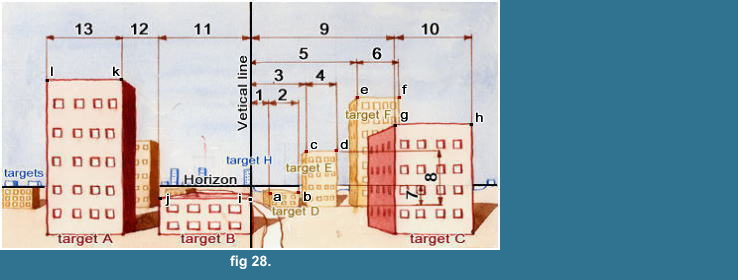 At first,
confirm (central) Vertical line and target B and H are on the Vertical
line. And you can confirm whethre your eye position is correct or not by
the alignment B and H on the Vertical line. (Step 5.)
Secondly,
measure "1"=distance between not target B and D but target H
and D, because the distance B and D is easily changed by the error of eye
position, I say again, then "2"
Thirdly,
measure "3" from the basic Vertical line=target H,then "4",
then "5" and "6".
Fourthly,
measure the vertical value "7" from the Horizon as the basic line, then "8". You may measure each vertical value for each target.
Fifthly,
measure target A, B and C on the layer 1, "9" from target H,
then "10","11","12","13"
When you finished to measure all the targents
on the layer, then you confirm your eye position
by Step 5 and measure the relative distance
between a target on the layer and a target
on another layer. And you proceed to measure
the targets on new layer. Then you do again
the same Step.
Attention!
I may suppose that you have been aware of the difference about measuring
between the layer 1 and the layer 2.
For the layer 2, the measurings are based
on the Vertical line,
target D from the Vertical line, target E
from the Vertical line, target F from the
vertical line
For the layer 1, the maeasurings aren't based
on the Vertical line, but the distance between
each target.
target A from target B, target C from target
B
Why?
For example,
each horizontal value is
5=1+2+bc+4+de
The equation is correct, unless the each
value contains the error.
But the measurement actually contains the
error, so the value of each side is supposed
as below.
The left-hand side= 5+error
The right-hand side=(1+error)+(2+error)+(bc+error)+(4+error)+(de+error)
Namely the right-hand side contains 5 error,
though the left has one error.
If the absolute value of each error is less
than 1mm, then the each side value is expected
as below.
the true "5" - 5mm < the value
of right-hand side < the true "5"
+ 5mm
the true "5" - 1mm < the value
of left-hand side < the true "5"
+ 1mm
Namely, the errors are accumulated by the
times of measurement.
But you can't always get the good result to measure everything by the basic
line. Because if the each value of measuring become much more than 150mm,
then the measuring itself becomes difficult, and probably cause the much
more error as I mentioned on Step 3, and the problem between the segment
of circule and the straight line arises, as I mentioned on 4-3-03-01.
We need to remember the nature of measuring based on the sepherical coordinates.
And as I mentioned on Step 3, we have confirmed the framing by measuring
characteristic building or landmark or point, the value less than 50 to
100mm, we had better to measure another objects to check whether the measurings
contradict those check-points or not.
See the fig 25, 26 and 27
The width of targets on layer 1 are more
or less about 50mm. Usually these values
are comparatively big, so we may measure
those from next to each other.
The width of targets on layer 2 are less
than about 20mm. We have to put neatly these
small houses and buildings between the detemined
distance, the above mentioned check-points,
for example, the target D and E between the
Vertical line and point "e" (fig
28)
We have to be able to determine which method
is reasonable for the case. And we are learning
by the practice. That is the experience.
That is the basic rule. We need to apply
flexibly the rule.
So the Horizontal line and Vertical line
may be also replaced by another easy recongnizable
or measurable line as a temporary Horizontal
and Vertical line.

Step 6-1-03
nother examples about measuring
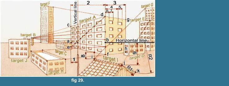 See target A
This is an example that each side of an object converges to a point on
target B. (fig 29.)
First,
Confirm Horizontal line and Vertical line by a level.
You have to check whether the horizontal
relative positions don't change by the vertical
eye position or not. If its changed, then
you have to straighten your back and measure.
You can make certain those below.
Horizontal line crosses with the vertical
line "df" at the point "b",
and you can memorize the point by the window's
upper line.
Vertical line crosses with the window's lower
line at the center of window. You can confirm
your eye position by this relative position
between window's center and a post .
So you can measure "1", "2"
and "3", and the vertical line
"ce" can be used as a temporary
Vertical line.
Then you do the vertical distance "ac",
"bd", "bg", and "ce",
"df", "gh".
You can get the vanishing point by extending the lines of target A, "cd",
"ef". And if you had drawn target B, you could confirm whether
the vanishing point on target B is correct or not by comparing with the
view with a bench rule.
By the same way, you can conform the extented line "dg" is on the corner of target F.
You can confirm whether your measuring is correct or not, to examine many
relations with another target.
As the skelton getting nearer to the finish, you can use much more relations.
Step 6-1-03-01. A way to detemine the arrangement of the windows.
As all the elements, windows etc. on the plain "cdef" are converged
and lined up for the vanishing point, then you can determine the position
of each element and draw by one-point perspective.
For example,
if you want to divide the line "cd" for 5 equal portion along
the depth, then you can get the 5 division lines by following process below.
( fig 29 )
Divide the line "df" for 5 equal portion, and draw the conveging
line from each division point to the vanishing point, and draw a diagonal
line "de".
The 5 division lines that you want are the
vertical lines on each intersection point
of the converging lines and the diagonal
line.
Then only what you do is to dispose windows
on each divided space. You did draw the window.
Step 6-1-03-02. Another way to determine the arrangement of the windows.
This is simple, you can do it to measure each horizontal and vertical distance,
"4", "5", "6", "7". ( fig 29 )
Though I think it needless to say, don't
measure the vertical distances from the Horizontal
line, but from the line "dg" or
"fh", for these windows are belong
to the plain "dgfh", then each
side can be the basic line.

Step 6-1-04
nother examples for measuring
See target l ( fig 29 )
Target l and a post on the left are belong
to layer 1, near distance.
So the relative distances between target
l, post and the other supposed to be easily
changed by your horizontal and vertical eye
position. Then you have to check whether
the relative distances are changed or not.
The horizontal eye position can be checked
by the position between a post and the window
of target A.
The vertical eye position can't be changed
beyond your body, namely you may just straighten
your back, when you have to check your vertical
eye position.
You can measure the distances from the post
about their horizontal positions of points
"i" and "j".
You can measure "8" from the line
"ef" and "9" from the
Horizontal line about their vertical positions.
You can also determine the position of point
"k", if you had the determined
two points. The intersection point by the
circles, "R1" and "R2"
is the position of point "k".
Step 6-1-04-01. Here I explane how to draw the roof tile of target l.
Step 6-1-04-01-1. If the size of tile isn't decreasing or hardly decreasing along the depth, then you can divide for equal portion.
Step 6-1-04-01-2. If the size is decreasing, then you can choice three ways below.
The first way
is that you measure every line.
The second way
is that you measure every 4th line, 4th, 8th, 12th, etc., then you divide each value by four for equal portion.
The third way
is that you use the intersection points by the diagonal line, mentioned
about target A.
If you can get the vanishing point by two
side of the roof, then you can deal with
it below.
If the roof has 20 lines, then you have to
draw 20 converging line and divide one side
for 20, but it is difficult and not practical.
Then you can use above mentiond second way,
draw 4 converging lines and seek 4 intersection
points for every 4th line.
If the each size of tile is much more than
5mm, then the first or third way is useful.
If the each size of tile is less than 4mm
and much more than 2mm, then the second is
better and practical.
Step 6-1-05. about our limitation of accuracy
You can't measure exactly each value, even
if you measure every line.
And you can't get exact intersection point,
even if you use the diagonal line.
You have to do those in the field, niether in your room, nor on your desk.
Can you exactly plot these value,
2.1mm, 4.2mm, 6.3mm. 8.4mm, 10.5mm, etc.
by the rule with the minium scale=1mm?
No!, you can't. And your pencile line itself
has the width, more or less 0.3mm
I used to plot those value as
2mm, 4.25mm=4+1/4, 6.25mm=6+1/4 or 6.33mm=6+1/3, 8.5mm=8+1/2, 10.5mm=10+1/2.
Those are also not exact, but enough practical for a picture. And I think
you will be able to divide 1 mm for two, tree and four parts, even though
it isn't exact, has only 0.5mm as a result accuracy.
And, if the each size of roof tile is less
than 2mm, then the house itself is small,
namely enough in far distance, needless to
examine the perspective effect, so you can
divide for equal portion.
These explanations about measuring are basic way, and useful as a practical
method, and I think you can find out and choice and apply the better way
for each case.

Step 6-2-01
easuring about a tree on layer 1=near distance
I omit the measuring about river or mountain, for those objects are rather
simple, I think I need not explain precisely for it, but just to briefly
mention to measure several points about their horizontal and vertical positions
,and you only plot its, then draw, so you can get the out-line. Then you
proceed to depict the detail of contour line by looking and examing with
binocular along that out-line
See fig 30
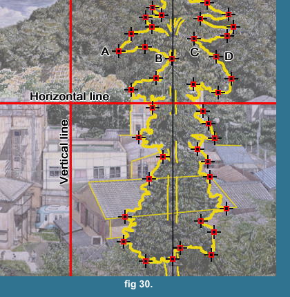
This is a cider. I traced its contour line, trunk and limbs by heavy yellow
line, and the out-line of houses and buildings by light yellow line.
The characteristic points are plotted as
red point. The points are grouped into three
kinds by the way of measuring.
First group
the points below the Horizontal line are usually determined by the horizontal
and vertical relative position with the objects surrounding the cider,
houses and buildings as available basic lines.
Second group
the points between A, B, C, D and the Horizontal line are determined by
the vertical relative position with houses and buildings, and the horizontal
relative position with the center of the cider, the trunk. So you need
to have confirmed which limbs are on the center line of the tree. We can
usually use the trunk and the limbs for the characteristic points to determine
the position of each details.
Third group
the points above the points A, B, C, D haven't the available objects near its, houses and building as the basic line,
but are determined by the distance from the determined two points with a compass, as I mentioned on 6-1-4.
The characteristic points that I mean have
to be easily clearly distinguishable from
others at any time by yourself.
Though I said about only the points on the out line, you can choice many
points for each branch,and you need to understand the tree as not only
the outer shape but also 3D objects constructed by each parts, the trunk,
limbs and branches with bunch of leaves.
Those recognition will help you to depict
the details, shading and coloring.
When you have finished the measuring of all
the points that you need, then you observe
the details with binoculars between two points
and depict the details of contour one by
one.
You need to observe carefully about each two points
whether the tendancy of the contour line is concave or convex,
then how many inflection points it has?,
whether its interval is regular or not?
how's its size between the top and the bottom comparing with the distance
between two points?
Much more questions you have about the contour,
much more precisely depict the details you
can.
The depicting about the details below the
Horizontal line will be easier by comparing
with the details of the objects surrounding
the tree.
For example, you can use the roof tiles as
a grid.
By the same way, you can measure the tree on middle distance. Then the measuring points will be fewer than the tree on near distance. And much more far the tree located, then you may just measre the height and the width. It's easy.
Here, you have finished the measuring about
main objects.

Step 6-3-01
 t is quite important that we are always checking out the
available relative positions with others and proceeding the measuring,
as I have mentioned on Step 6-3.
We need to check out these three points.
Point 1
t is quite important that we are always checking out the
available relative positions with others and proceeding the measuring,
as I have mentioned on Step 6-3.
We need to check out these three points.
Point 1
the horizontal relative position with other objects
What objects are at the both side of the object?
And those are really the same as the sight?
Point 2
the vertical relative position with other objects
What objects are above the object? and below?
And those are really the same as the sight?
Point 3
What objects are on the extention line of the object?
This is quite useful to confirm or determine the slant of roof, converging
line by Perspective.
I used to choice the distantest object on the picture plain to get rid
of a plot error. (fig 30)
But you need to be careful to do that, for you need to considerate the
effect of barrel shape by the spherical coordinate measuring, as I mentioned
on 4-3-4, (fig 15).
Especially you need to be careful for the
peripheral part of picture, because the curvature
becomes bigger according to the distance
from Horizon and Vertical center line. So
I have explaine again and again about Horizontal
and Vertical line.
Indeed I have confirmed the object on the
extention with a straight bench rule by my
sight, but the sight is sight, the picture
is picture by the shperical coordinate measuring,
naturally shapes the barreled grid for two
straight center lines, Horizon and Vertical
center line.
about Horizon and a Vertical line.
More or less you will be faced by the disagreement
with the measuring, especially on peripheral
part of picture, four corners. Then you need
to remember the effect of barrel shape, and
seek the practical solution.
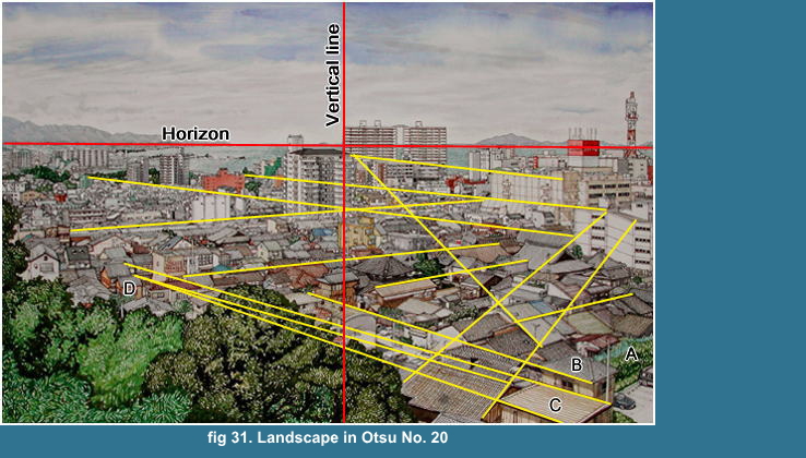 See fig 31
,
I could confirm with a bench rule that the house C and D were on the same
straigh extention line, but I think that extention line may be curved on
the picture plain by the effect of barrel shape, because the extention
line is far below the Horizon. Namely I suppose the angle of the roof line
C is getting probably smaller to horizontal line as it is getting much
more far from the Horizontal and Vertical center lines to the peripheral.
The space of A and B are actually much bigger than the value of measuring
by the abovementioned reason.
I have mentioned about the cause of that disagreement on Step 4-4, the
aditional explanation.
You may soon be aware of the fact by seeing
the extention lines on fig 31, that you can
never construct the whole view of a landscape
by the artificial drawing method, like One
or Two-points Perspective.
Because the arragement of real houses, buildings
and structures aren't always built or deposed
at right angle each others, on the contrary
a regular desposition seems rather exception,
so you can never apply such a simple Perspective
for a real view.
Still you can apply the One-point Perspective
partially for the groupe of houses or buildings,
and that may help you understand clearly
or logically the desposition by the simplification.
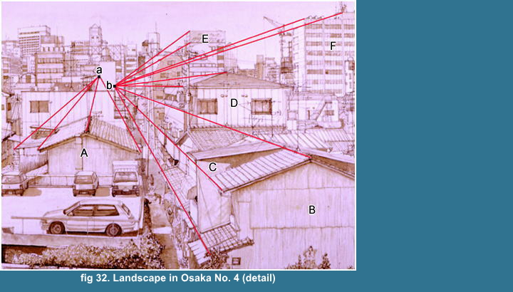 See fig 32
The house "A" belongs to the vanishing
point "a".
The house "B", "C", apartment
house "D", buildings "E"
and "F" belong to the vanishing
point "b".
Here you have finished almost the process
of measuring, I think you will have spent
40% of total amount hours of the work only
for the measuring.
For example, I think I needed probably 40
hours/ 4 weeks, 10 hours/2 day/week, for
the measuring about the Landscape in Otsu
No. 20 (fig 31), the total amount hours of
work 92 hours.
I gess you think it too much only for measuring.
But I think these troublesome work is not useless. Because you will have
observed the changing of lighting, weather conditions and the variety of
appearance of the view until the finish of measuring.
You will be gradually constructing your image
of your sight. Those observations will give
you enough imformations about the view, make
your image rich with the details, and heip
your decision about the next process, shadowing
or coloring.
I think this steady working is quite different from a photo, a picture
is the image of an average impression during a particular period of time,
but a photo is the image of a momentary impression that gives us sometimes
very diffierent and unknown impression from our own image about familiar
sight.
If you have luckly finished the measuring
without any contradiction, that will make
you feel simply the great enjoyment about
your exactness.
But what you can get by the measuring is
bare an skeleton drawing with straight lines
by rule and a bit of free lines by hand,
that, I suppose, doesn't look like a picture
for you but a mechanical drawing, or an almost
blank sheet with few line.
Actually, I think you can't recognize anything but a blank sheet, if you
see it from more than 1m distance. And it is really a horrible sight that
a man with just a trunks is sitting still and silently in front of an blank
sheet of paper for 5 hours, almost motionless and is staring at houses
with binoculars from a hill for much more than a month, I think by myself
it really horror, still, whatever people felt and thought, indeed I was
by myself greatly enjoying it.
I can suppose that everybody can get almost similar result, about same
framing, same view untill here, if he had have enough experience about
my measuring method. But you can choice many different expressions from
here even for same realistic landscape painting.
Everybody can say it easily only by his or
her mouth or by his or her camera that a
realistic landscape is
only to reproduce the view. Who can reproduce it? Such word has nothing
for contents.
I will explain each expression by each example,
along each my work. So I explain from here
only the process briefly.

Step 7
 bserve the objects with binoculars and determine the figure of the objects
and depict the details by pen.
bserve the objects with binoculars and determine the figure of the objects
and depict the details by pen.
You need to finish the pen drawing first about the layer 3=far distance,
then the layer 2=middle distance, at last the layer 1=near distance.
Those reasons are below.
First reason
once you had drawn something by watercolor, then you can never erase it
again, and you can't lighten your watercolor, but only darken it.
Namely, most charming and vivid parts as
the subject of the picture should be finished
at lastest, because its are usually the most
bright and high contrast parts. The other
parts should be colored according to the
order of the whole.
Generally, we sense the brighter and higher
contrast object being nearer than the dark
and dull one.
Second reason
the working to dipict the layer 3=far distance is often monotonous and
troublesome, needs patience, I think, can't be done sufficiently after
the enjoyable working about the layer 1=near distance.
If you did your best about that monotonous parts, the layer 3, then you
can do naturally much more better finish about the layer 2 than the layer
3. I think you can't do that by the reverse order.
I haven't anything to explain as a general
rule or process about expression, for I am
now seeking the best solution too, and if
I thought I had found that best solution,
and if I was applying that same process like
a sterotype, I think, my watercolors had
been nothing but a mechanical process, like
a camera fix an image on film.
A colloapse then begins and ceases to be
as an art, perhaps. An art is curious.
Am I doing that?
Step 7-1. Finish the layer 3=far distance part
If you choice the fine day as the lighting
condition and you want to finish your watercolor
by full coloring, you need to examine carefully
and remember the shadowing of objects, and
its color.
And I think it better that you finish the
details part by part completely, if you can.
But I think I can say it honestly that you
may need quite enough experience to do that.
You may do the coloring after when you have
finished the drawing, if you have enough
time and patience to do that. For you need
very long time waiting the same fine day
for coloring and to maintain your concentration
to your watercolor until the finish.
If you want to finish your watercolor by
monochrome shadowing, you may finish the
drawing at first, then the shadowing. For
this time, you need to be careful only for
the shadowings of objects. It is much more
easier than the full coloring.
So if you want a steady process step by step,
then you had better to practice the monochrome,
then the full coloring.
Anyway, I think I can say that the solution
that now I use for the expression about the
far distant view is reasonable, so I explain
here it as one example.
See fig 33, 34, 35, 36
These are the details for the example expressions
of layer 3=far distance
These are watercolors, the material, watercolor itself limits the expression.
And the sheet size of these watercolor is
small and it also limits the exprssion.
And you have to do these work in the field, open-air limits your working
as well.
You need to consider these conditions.
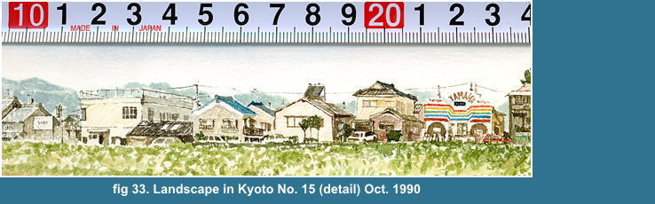
I depicted the detail with brush by eye observation
and measurement. (fig 33) I didn't use here
the contour line for dipicting details. So
the expression is primitive but much more
natural than later works, I think.
See the detail of the window of a house below the scale "13". I didn't use contour line to depict the sash bars but expressed
it remaining as blank, papaer's white, and windowpanes are colored with grey. The parked white car in front of house below the scale "20"
is also dipictied by same way, the figure is expressed by the color of surroundings and its window.
These expression without contour line needs much more working times than
that you might suppose.
But I can't apply these expression without contour line for much more complicated
landscape.
Because I have to express one side of a house with the different value of light or color that make you understand
the boundary with the other sides or surrounding objects.
So the condition of lighting becomes essencially much more important to
the expression.
Indeed I think I have said many times about that, you need to wait coming the same condition or
you can't unify the impression of your picture, like one detail is high contrast, the others are dull, then each detail may give confusing impression each other.
I used usually Whatman paper until 1991 because of its whiteness. But Whatman papaer's surface is very weak, so you can't use eraser not to damage the sized surface of the paper.
So I didn't do rough drawing by pencile except
a few slightest marking that needed not to
be erased. I hadn't enough time for landscape
painting as 1989, so I painted my watercolor
directly by watercolor with a brush since
1990 to 1991.
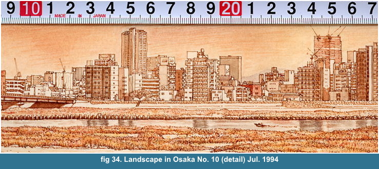
See fig 34
This is the first work by my drawing scale. (fig 2) My drawing scale is
very useful for such detail. You will be able to measure it perfectly.
That details are depicted by contour line. The size of small windows are
less than 1mm. You can't express those small details by brush, and even
if you did it, you can't make someone understood what you wanted to express.
The result will never compensate your troublesome labour with that effect.
I think a contour line is the simplest and most effective meaning to
explain what it is for like those small watercolor.
Here I used to keep a pen point sharpen to depict very small details. I
think you can understand that expression, that each smallest object itself
is depicted by only contour line, has only their out-line and windows,
has nothing flavour as a independant object for a picture, but is gathering
up as the town probably to successfully make you feel the atomspher.
What I wanted to paint
as I felt is also able to express by the object itself existence.
Here, what I did is only to depict the objects that I could do. I didn't find any separation between my sight and feeling, between A Subjective and An Objective.
For such distant object, we can't find anything
but the contour line. If you keep the ratio
of the size between each object, you can't
depict anything but the out-line for those
small objects and shadowing.
Jan Bruegel elder is known by his detailed
depiction, but I think he mistook the ratio,
especially his persons in his picture, he
painted those for too much bigger to depict
their details and by too much higher contrast
and color. So that gives us strange and confusing
impression of the space. I think he had to
deal with those miniature persons by the
expression like a Monets.
He can never be matched to his father only
by that details.

Step 7-1-01
 ow to draw layer 3=far distance, smaller details?
First,
you measure the position of the outstanding buildings for others.
Then you are depicting the smallest objects
one by one, puting into neatly between the
outstandings.
You need at first to recongnize the shape of each smaller object with binoculars, what it is and how it is?
If you didn't recognize the shape, then you
can't depict it. You have to measure the object that the size
is much more than 5mm, or it is better.
The vetical value is very clear and easy
,here I can use the bank line of Yodo River
for the basic Horizontal line.
But I need patience to measure the horizontal
value, still I can use each side of outstanding
buildings for the basic Vertical line.
When you have measured the outside dimension
of the smaller object, then you depict its
details directly by pen and watercolor, the
row of windows, observing with binoculars,
by eye measurement. If you have determined
the lighting condition, you have to examine
where the shadows are casted on and you give
the shadows.
For example
I think I probably choiced the lighting condition as 3 to 5 p.m. in fine
day. I used to work from 10 or 11a.m. to 5 or 6 p.m. untill 1994. I was
only measuring and drawing the conture lines until 3 p.m. coming the same
lighting condition, or coloring the part not influenced by the lighting
condition, after I had finished the measuring about the lay-out until the
Step 7.
After 3 p.m., I was very busy, I have to measue, draw, depict and also do the shadowing always watching the shadows moving.
Because the shadows of evening light are
quickly moving and passing on the structures
and the earth. You have to be careful and hasten to depict.
You can't understand the situation only looking
the other painting.
See the bigger building below the scale "24". This is the building
of Nippon Paint Co., LTD. The building casts its shadow on another building
below the scale "18", that is the building of The Mainich Newspapers,
or, the shadow may be the building itself's, for I remember both wings
of the building bend at 45 degree to the center part, if I didn't misunderstand.
(fig 35)
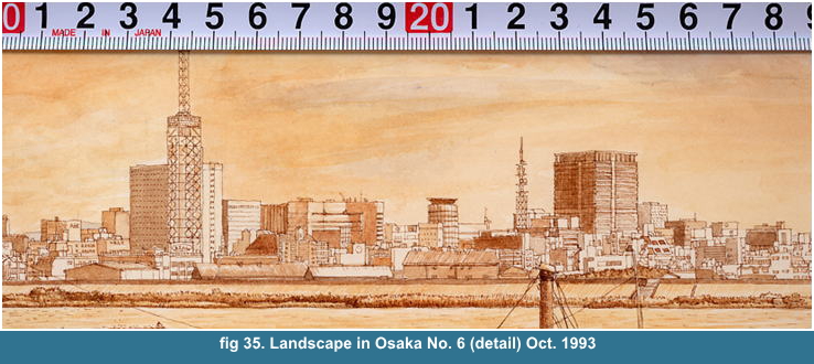
What I want to say here is that you need always to be careful of each shadow
moving, especially before and after the best lighting condition. Those
shadow makes the details much more vivid and gives the solid image to them.
You have only 2 hours to be able to use for
the shadowing for a day. And much more smaller
the object you are going to give the shadowing,
much more time you need to confirm again
after the drawing, which building that you
have drawn is. So, for such smaller object,
you need to proceed the measuring, drawing,
depicting and shadowing at the same time
not to waste much more time, before forgetting
the memories.
So I said it is better to measure, draw,
depict and finsh at the same time about layer
3 a part by a part on this Step 7, as I mentioned
on Step 6-2.
And I think you have understood that you
can express sufficiently only by the contour
line and shadowing for the smaller details.
See fig 35.
I can say same thing about Landscape in Osaka
No. 10, except I used the heavier line and
much more definite expression, higher contrast
than No. 6.
You can see the surface of Yodo River between both side of bank, that reflects
the silhouette of buildings, and a boat is being driven.
The river reflects the silhouette, and that
means there wasn't wind blowing. If wind
blew harder, then the river was reppled so
that the surface reflect regularly light
like fragments of diamond. The impression
of a river, sea are very changealbe by the
condition of weather, wind and light, because
its reflect the surroundings.
I don't know whether you know those things
or not. But you have to determine a condition
from several choices and assemble them for
reasonable order, because you can't do it
like a camera at a moment.
I can suppose that you judge easily those
detail as the common result that anyone can
depicted as only those were. Of course those
had been there, but we aren't camera, we
have to be reading and choicing one by one,
for limited periods, by our taste, in reasonable
order.
This is painting, As we can take personal arragement, permutation from
only 8 characters, like a password, we can naturally choice many things,
so many things from a view than that password.
Actually you don't paint the same picture as the others for a same view.
That isn't mainly the result of your technique itself, but rather your
reading and choice and volition about that view, that the fundamental elements
determine the technique
I think I can say that a painting is similar to a reading, nobody say that
he has read and understood the book just becaue he bought it, or he has
been watching a TV just because he turned on the switch.
The state, reflecting the view on our retina is just to buy a book or to
turn on the switch, we can go out left the book on a table or left the
TV being turned on, it's just reflecting automatically without our consideration
by our brain, or somebody say he did?
Namely, the image on our retina is almost
same for evryone, can never mean that we
can paint realistically the view as it on
our retina. There are many choices and enjoyment
how to express it by limited means and our
ability. A man who says the realistic painting
is only rerpoduce the view, says only about
the state that the image being reflected
on his retina, does never think how to take
the image out from his retina on a paper.
So you have to always be prepared for shadowing
and coloring which condition you should choice
from the begining of measuring. You have
to read and learn by the view, or you can't
depict the details, I think.
I felt sometimes that a monochrome coloring
is much more suitable for a landscape watercolor
that has many those smaller details than
a full coloring.
For I can read those attractive smaller details
and also explain that eloquantly. Because
a color itself has independantly a particular
order for a Perspective. And that makes the
Perspective effect confused.
For example, Red is coming nearer than Green
by the impression at the same value of chroma.
And the nature of the watercolor material
itself makes the coloring difficult.
For a higher chroma color darken the picture. So you can't get the same result as the oil,
acrylic painting materials and gouashe, able to cover the basement completely by the material.
But watercolor is still attractive material
for those characteristics, quick dry, high
quality pigments, above all never damage
the texture of paper.
I can paint much more realistic, if I use
gouashe. Because it has strong ability to
cover the basement, that doesn't darken the
picture even by using high chroma color,
namely easy to control full color painting.
But the ability to cover the basement by
the material naturally cause to cover the
texture of paper by the substance of gouashe,
the harmful damage to the texture, like spreading
and pasting mud on a sheet of clothe.
Watercolor paper itself has the high quality texture can never be comparable
with the other basements. Since 1991 I use Aquarell Arches Satine, has
very fine texture. This paper has quite strong gelatine sized suface and
exquisite and excellent texture. Gouashe covers the texture. And this is
main reason not to use Gouashe, indeed, I don't like it, it is too heavy.
So you need a solution to handling watercolor for the natural expression.
You can quickly recongnize it, what I said, as you have done it.
For example,
if you spread manganese blue or cobalt blue over a sheet, deeply impressed
by the fine blue sky, then you will find it has turned to be dark night
sky, very dark, almost nightmare.
And you can never make it brighter, without
scraping and getting rid of the whole surface
of the paper covered by the pigment.
See fig 36
Surely, here are the problems that I have to conquer, still remains.
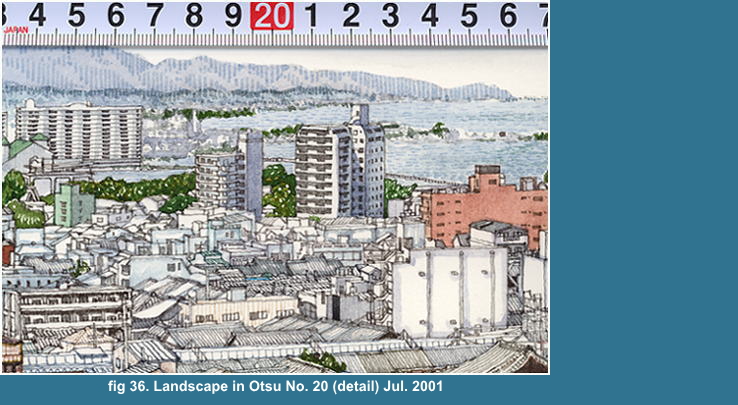
Anyway, I depicted the smaller houses only
by the contour line and gave the color just
to cover the contour line. And the line is
heavier.
These far distant parts in fine day are generally
losing their color to violet-grey accoding
to their distance. A green and a brown building
are only given their color.
The roof tile of smaller houses itselves are black. But if you paint them
with black, then their contrast will become stronger, then their color
give the impression their being much more nearer than their rational distance.
And I think I can express sufficiently those far distant parts' color only
by the color contour line.
And if you painted and cover the whole those
part by their color, those became too darken
and the impression of the picture became
too heavy.
You can see the whole image of No. 20 on
fig 31.
This is one of my solution for watercolor,
that I determined I make the color of each
contour line represent the color of each
samller object itself and keep the picture
bright by remaining the blank space, the
material white of paper.
So I used the heavier line to be able to
much more impress their color.
Watercolor materials have the diffirent values
of their ability to cover the basement. Those
nature also make the handling difficult,
I think.
And especially watercolor material contains
water as the medium, that will be vaporized
soon, then the bare surface of paper will
appear on the part where water had bee there.
Namely, the conditions of reflecting light
are different according to being wet or dry.
The brightness of watercolor painting is
depend on the materical white of the basement,
paper. Light is reflecting on the surface
of paper through between the pigment particles
of watecolor material. And light is also
reflecting on the pigments, that make us
the color.
So the impression of color is the synthesized
two sensed colors, the basement and pigments,
like, black dots painted regularly on a white
sheet of paper makes us feel the grey sheet
of paper. Everyone probably knows it. I can
say it about color too, like a principle
of TV.
Oil painting material, acrylics, gouashe,
these materials reflect whole light on their
surface or their layer of material, indeed
oil painting is also depend on the brightness
of basement, but its medium, linseed oil
is never vapourized, but polymerized with
oxygen, namely the condition is less changable
whether it is dry or not than watercolor,
and if it contains few linseed oil, like
impressionist method, then it reflect light
completely on its surface.
You may be only careful of the brightness
for monochrome coloring. But you have to
be careful of two value, brightness and chroma
for full coloring. And watercolor material
is difficult to deal with for such values.
So you need to devise the expression.
I think there are main two points for watercolor.
First point is to keep Brightness for high chroma.
Second point is to keep Readability, especially for those that contain many smaller details.
you can't get the satisfactory result for brightness only to paste high
chroma watercolor material, as I have mentioned former, for it only darken
the picture.
And I think that an usual watercolor painting method, Wash, or Wet on Wet
is helpless for realistic expression and detail depiction, except for sky.
And that are the typical sterotype and obstinate idear about watercolor,
that people think easily watecolor means only Wash or Wet on Wet expression,
that I hate, not for the method itself, but for their obstinacy.
I think the dipiction by color-contour line
is very usefulf expression for that two purposes.
Because I can keep the Brightness by color-contour
line to remain the blank space, the whiteness
of the paper, and the contour line is effective
to the readability of the details.
See fig 36,
how to draw the details
Fundamentally, the Step is the same about
7-1-1, here first you have to measure the
buildings that you can recongnize easier
than the other smaller details.
There are 6 buildings surrounding the smaller buildings or houses, like a colony or an island.
At first, you measure and draw the boundery, then you draw the inner part
one by one observing the objects with binoculars, you may measure the smaller
details and you may do by eye measurment, both you can do.
You need patience especially to depict these
smaller parts, for you can't quickly draw
them but very slowly and in steady way, and
you need to sometimes change the color to
draw the contour line of each part, and those
changes are very small part and slighter
and modest for your labour.
See fig 36,
the part below the scale 17 to 19, just below the mountain
I didn't use even the countour line to depict those details to make you
feel the distance.
I depicted it with brush and gave them the light and shadow by the grey
Wash, and I used vertical Hatching to give the solid image and the shadow
to the mountain

Step 8
 inish the layer 2=middle distance
You can find out many enjoyments about objects
on the layer 2, for these parts are enough
big to depict their details, you can feel
the tangible quality about them.
So, if you saw something, then you need to
recognize clearly them, what it is, with
binoculars, and you have to depict them.
The important thing is that you must never
judge which object you depict or you don't,
by your taste or the evaluation about their
utility, but you have to depict all that
you can see and recognize, everything.
Don't bring your taste and the evaluation
about the object itself into the picture!
We have to choice the weather condition,
we have to choice the moving objects, we
have to choice the expression, these are
influenced by our taste, those are naturally
the matters of the picture. But the objects
are object independantly there, by their
order, we are going to reproduce it, so we
must never confuse it by our taste, unless
we can't do it.
Step 8-1. How to draw layer 2?
We need to apply some stylization for layer 3. But we need less stylization
for layer 2.
Generally, smaller an object becomes, stronger stylization we need to depict it.
Becasue we can't reduce it to keep every ratio about its details like a
copy machine, computer graphic, camera.
So I can say here, simply, "Depict as what you are seeing"
And you can see the shape of each parts about layer 2.
And you can get each figures by the above mentioned method of measuring
by the drawing scale, if you can't draw it by eye measurement.
You can see clearly the shape of each objects for layer 2.
And you can see slightly also the tangible quaiity about that material.
So you have to depict not only the shape
but also the tangible quality, the texture
of the surface for the object on layer 2.
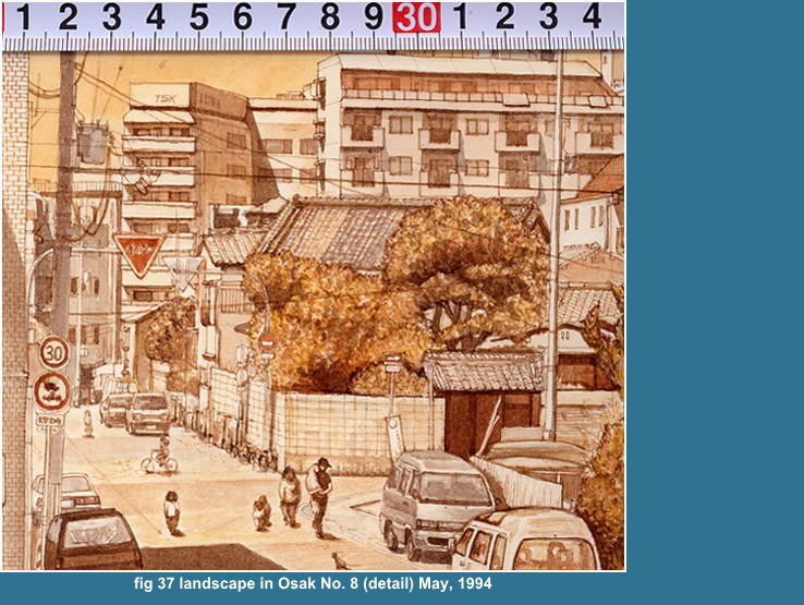
See fig 37
The object on layer 2 is enough big, so that
the object depicted only by the contour line
can't have reality without the tangible quaility.
You can see two cars faced on each other on the right hand lower coner.
I think I depicted the cars very well, you
can feel the tangible quality, its smooth
surface of the body, metalic glare, front
window, headlights.
I remember the color, metalic silver, silver
grey. I depict the bonnet with gradation,
so the left hand corner reflect light, and
each corner as the highlight part.
The roof tiles on the center slightly change
its tone at the quarter from the left side.
You can't finish the trees only by the contour
without the tangible quaility, its leaves.
There are a man and woman, probably his wife and children, their family.
The man lifts up his dog on the shoulder. And a little girl is riding her
small bicycle. And a cat is sitting.
I really saw those persons and a cat. I have
seen peoples coming here to enjoy their walking
along the bank of Yodo River on Saturday
and Sunday. I felt it lovely, so I put those
objects into my watercolor.
I am constructing the details by adding those
persons one by one. Of course, you have to
remain those space blank where the persons
should be painted on, until you have finish
its.
These persons in this watercolor, will soon
disappear from the framing, are your choice.
You have to build up you image of the scene by your observing as a much
more characteristic, suitable view. You can see the logo "TSK"
on the top of a apartment building. I remember the representative "TSK"
was to be soon summoned in Japanese Diet for his company's bad debt.
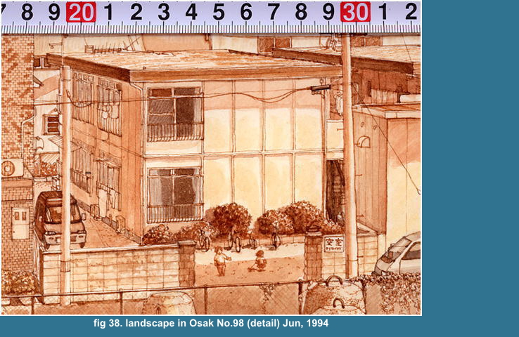
See fig 38
Here you can see the fence made of concrete
block. And the number of block is exact.
And you can see the part of tiled wall at
left hand. And I counted the number. And
the disposition of dark color tiles is exact,
though I might miscount it for one line,
or so.
At the gate two littl girl are playing, one
of girl keep a kitty by string. She was very
bad, hung and swung the kitty, a poor kitty.
This apartment house was replaced by an apartment
building later.
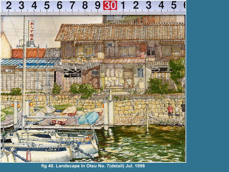
See fig 40
I like the dike, that is coverd and piled
up by stones. The stones are irregular shape
each other. The characteristic feature is
well expressed, I think. The dike is built
up by the combination with smaller stone
and rather big one, but that top is neatly
leveled.
Those are countable, one by one. It seems really troublesome, and was really
so.
You will be able to do it,
then,
why don't you do it?
See fig 38
This is the prefabricated apartment house. I think the panels were undulating,
so I gave the patial wash to the front panels.
See fig 39
I like these details, very crowded houses,
and the confusing, but there is a daily life.
A train, Keihan railway's is running through
between the houses, is coming out and showing
its head just behind houses. There are a
chair and ladder in front of tin roofed house
behind a green roof, a man is crouching forward,
doing something at his small garden. A dog
is kept, laundries are hung at vacant place
at the right hand lower corner. A man is
coming pushing his bycile and behind his
back a moter bike covered with blue sheet
is seen.
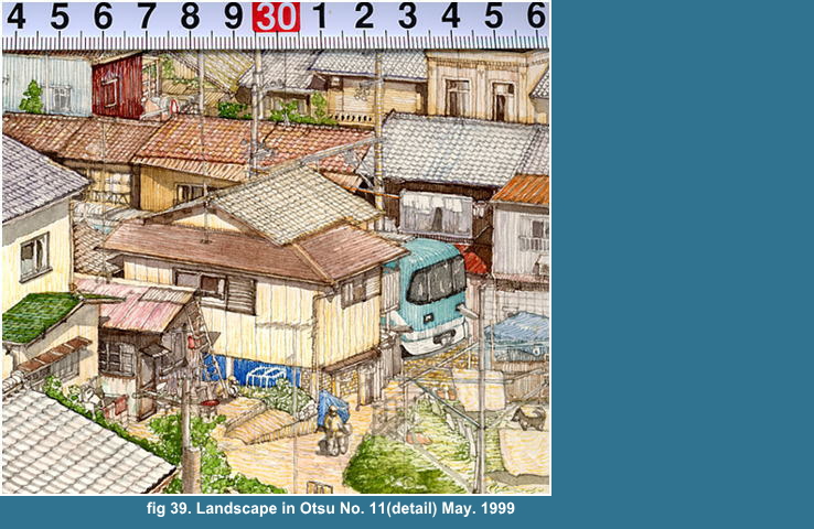
fig 40. Landscape in Otsu No. 7(detail) Jul. 1998
See the dike covered by piled up stones,
irregular shape. I might be proud of it,
not because of my technique, but because
my attitude being sincere to the object itself.
That arragement is exact. These are countable.
If you had counted up and drawn its, then
those were gathered up and naturally showing
their character. I don't need any style to
express it but just to draw it as those are.