There are various Cartridge/Arm Alignment Gauges which do not comply with Baerwald type alignment though Baerwald type linear offset around 93.5mm is almost universally accepted for 30cm LP now. Some alignment gauges should be applied on specific designs of arms only.
I collected various designs of alignment tools as under.
DENNESSEN Alignment tool: US Patent 4,295,277 (Year 1981). Trade name "GEOMETRIC SOUNDTRACKTOR"
"Geodisc" Cartridge alignment system: US Patent 4,326,283 (1982) invented by Toulan etc and assigned to Quality Audio Components - it is interesting to note that Toulan was also co-inventor of previous patent for DENNESSEN. This variation of Dennessen utilizes a sight line in the form of a raised ridge which is aimed at the pivot point for the tone arm. There is no difference between Denessen and Geodisc except that Denessen uses inner null point and Geodisc uses outer null point based on the same linear offset length 93.4mm i.e., optimum null points of Baerwald type alignment: 93.4+/-27.4mm. Null points are determined by linear offset length (93.4mm in these cases) +/- suitable alignment alpha (27.4mm in these cases). Thus every arm with fixed offset length irrespective of effective length has potential for aligning on the same 2 Null Points as designed. What makes difference in arm geometry is to design optimum linear offsets in accordance with the groove radii of music band to be played on. What makes difference in arm alignment is to set the optimum alpha as designed. Actual null points variations (i.e., alignment variations): Linear offset +/- alpha.
Townshend EEI Alignment Gauge: US Patent 4,351,045 (1982) for Lateral Tracking Measuring/Alignment Tool for Arm (claim priority, application GB July 1979). The inventor including many other persons referred erroneously to IEC minimum radius of groove though IEC has not specified any except for transcription/non-commercial disks.
Phonograph cartridge alignment template: US patent 4,368,527 (1983) invented by Goldstein. This plate combines angle alignment on mirror and overhang alignment around the centre spindle with spiral curve line. This invention refers to an article entitled "Cartridge Arm and Turntable vs. The Groove: Who's Winning?", in the July/August/September 1977 issue of the "Audio Critic" about optimum cartridge alignment. Goldstein explains as under (in italic):
The author (Peter Aczel) provides a table which relates effective tone arm length to the required offset angle and overhang.... Unfortunately, the procedure suggested in the Audio Critic article is relatively complicated and cumbersome. Initially, it is necessary to measure the effective tone arm length, (i.e. the distance between the stylus and the pivot axis of the tone arm). Next, the tone arm is pivoted over the center of the turntable and the distance between the turntable spindle axis and stylus (i.e. the overhang) is adjusted to the value indicated for the corresponding tone arm length in the table. While making this adjustment, it is likely that the effective tone arm length will be changed, so that repeated tone arm length measurements and overhang adjustments are likely to be necessary until the optimum combination is achieved. With this done, the offset angle is adjusted by twisting the cartridge until zero tracking error is achieved at the Baerwald radii. This latter adjustment, however, interacts with the arm length and overhang adjustments, so that it may then be necessary to repeat all of the preceeding steps several times until all of the adjustments are simultaneously correct. What complicates the alignment process even further is that no reliable procedure is disclosed by the Audio Critic article for determining when zero tracking error is achieved at the two Baerwald radii. This is no simple adjustment and, until the present invention, could only be done very crudely by eye.
Broadly, it is an object of the present invention to achieve optimum alignment of a phonograph cartridge without performing a complex, multiple step, repetitive process. It is a specific object of the present invention to provide a method and apparatus for aligning a phonograph cartridge which achieve the foregoing object.
In order to use gage 50, the apparatus 20 is mounted on turntable 12 so that aperture 20a receives spindle 14. The gage 50 is then mounted on top of apparatus 20 so that aperture 50a receives spindle 14 (see FIG. 5). Inasmuch as gage 50 is transparent, the lines 22 and 24 of apparatus 20 are visible therethrough. The apparatus 20 is then rotated so that line 22 extends between the axes of spindle 14 and pivot 16, as when adjusting for optimum overhang. The tone arm 15 (as represented by the dashed line 40 in FIG. 5) is then positioned so that the tip of stylus 19 lies over line 24, and gage 50 is rotated until the spiral curve 54 intersects the line 24 at the point where the tip of stylus 19 lies. A very close approximation of stylus overhang is then obtained by reading the value at which the line 24 intersects the scale 52.
It should be noted that precise stylus overhang would be measured if line 24 formed an angle of 180 degrees with line 22. However, only a negligible error is introduced when line 24 forms an angle with line 22 which is close to 180 degrees, for example 170 degrees. This angle between the lines 22 and 24 is provided so that the tone arm need not be brought near the spindle 14 in order to make this measurement.
The preferred embodiment was designed for use with a phonograph for conventional 12-inch records. In this case, the two Baerwald radii are 66.04 mm and 120.90 mm and the fixed point is at a distance of 89.323 mm from the center of aperture 20a.
The last statement about 89.323mm distance mark (#32 in the drawings) as the fixed point may sound puzzling while outer null point 30 (120.9mm?) and inner null point 34 (66.04mm?) are indicated as normal Baerwald type null points calculated for 12-inch records. This fixed point 89.323mm is designed for adjusting overhang without overlying arm over the spindle. Equation [d =SQRT(L^2-(L-O)^2)] along with Table 1 of Baerwald type alignment data is indicated. Exact 89.323mm can be obtained from another equation d=SQRT(Null 1*Null 2) when null point set is calculated 65.998/120.891mm based on outer groove radius 146.05mm and inner groove radius 60.325mm. But actually every record has different inner (and outer) groove radius for music so that any fixed idea on alignment is meaningless in fact: first there is a record in front of us! This fixed point 89.323mm for overhang adjustment is not null point for angle adjustment-see my trial drawing for further explanation. The inventor knows well about overhang, but the reader/user may misunderstand the real meaning of overhang (=effective length L- arm distance D). Strictly speaking the overhang should be measured when the straight (imaginary) line from stylus to arm pivot should cross the centre of turntable spindle. Very often even in audio magazines etc: offset angle is erroneously taken as shell offset or wand bending angle, and overhang as stylus tip distance on longitudinal shell centre which is crossing on spindle. Please think about imaginary=ideal lines for strict definition. The fixed point for this overhang adjustment has an unique merit that overhang can be adjusted irrespective of arm length or arm distance since the overhang can be adjusted properly in accordance with fixed alignment design of arm. This fixed point (#32 in drawing) on overhang adjustment for other alignment design can be modified: 84.163mm=SQRT(60.325*117.421) for so-called Stevenson or 90.529mm=SQRT(70.285*116.604) for so-called Loefgren and so on.
This alignment tool looks attractive as combination of LENGTH ADJUSTMENT (stylus location adjustment) & ANGLE ALIGNMENT: [first step] set overhang per fixed point and [next step] adjust angle alignment on one of null points - when overhang and one null point are set properly, second null point can be used for reconfirmation of alignment. Then why this device was not popularized? When applying this device, it is essential that the line 22 must aim exactly at the centre of arm pivot. But arm base at the same horizontal level as record on turntable (approx. 2mm+mat thickness+platter level) has often irregular form or is inaccessible directly even if this alignment tool is equipped with forked ends to fit it on the round arm base. Theoretical good design is not always practicable.
Pickup adjusting equipment: invented by Peschel and assigned to AKG Akustische und Kino-Gerate Gesellschaft m.b.H. The adjusting device has an L-shaped cross section and orienting gratings on the legs thereof for aligning the pickup and pickup arm when the stylus of the pickup is received on a contact point provided on the device. This tool was supplied together with AKG cartridge model P25MD.
Tonearm alignment gauge: US patent 4,490,816 (1984) invented by Kehl and assigned to Shure. This device adopts two null points method though specific null point location is not clarified. This device is not universal since the receptacle for cartridge body without stylus holder has to be designed in accordance with respective cartridge body.
Further development from above: definitive alignment method for arm distance & overhang & stylus direction angle invented by Graham and applied on his arm Model 1.5 etc. Mounting distance from arm pivot to the centre spindle is adjusted by sliding the arm on SME-like base plate [Fig. 5A/5B/17/18]. Overhang (stylus tip location) and cartridge angle (stylus cantilever direction) for predetermined offset angle can be adjusted on shell using alignment device [Fig.19]. Thus it is possible to align the arm and cartridge just as designed in original geometry of arm (user-friendly=not allowing alignment error at user's end nor deviation from original geometry design of arm).
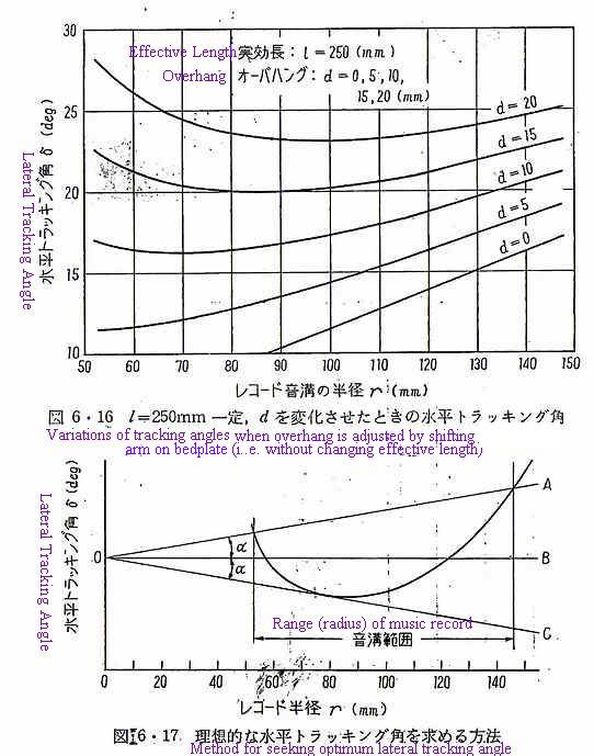
STYLUS ADJUSTING STRUCTURE FOR RECORD: US Patent 3,493,234 invented by Voss etc and assigned to Electroacustic Gesellschaft m.b.H in Kiel (ELAC). Fig.1 shows variation curves of the tangent angle α with respect to the groove radius R in various overhang designs: curve 1 shows variation at 0 overhang. Of course in this patent, two points (5 & 6 in drawing) alignment method with due overhang and offset angle (4a) is selected as optimum. Fig.2 & Fig.3 are based on different embodiments. This device (overhang checker) was equipped on Elac Miracord 50H (4-speed auto-changer) & 50HII(3-speed auto-changer) etc. My note: If Tangent angle alpha in Fig.1 is meaning "tracking angle", then Ri and Ra in Fig.1 should be reversed. In case of 0 overhang (curve 1): Tracking angle should decrease toward inner groove radius. See Fig.6-16 by JVC in the end of this page and the Design sheet in my armtrack.xls. So I assume "Tangent angle" = 90 degrees - tracking angle. See details at ARM DATA(html) and its GEOMETRY OF ARM(drawing).

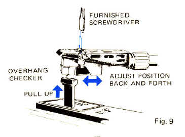
Overhang adjustment at arm rest position is also adopted for some record players in the past. The following overhang checker was adopted on Pioneer PL-12D/E, PL-25E, PL-M12/M25 & PL-31E etc around 1973. This device is especially effective for the kind of arm which cannot stride over the spindle due to the limited swing angle design at pivot.
Simple measuring tool of tracking error angle.
Percy Wilson was the pioneer of alignment matter too. He is introduced in Gramophone Museum with downlodable link to “Modern Gramophones and Electrical Reproducers,”(pdf) with George E Webb in 1929. In SP era, underhang alignment with only one null point was popular. Inside force at outside was considered rather preferable. Interestingly USP2277344(1942) indicated magnetic bias at inner groove in order to compensate outside force due to underhang alignment.
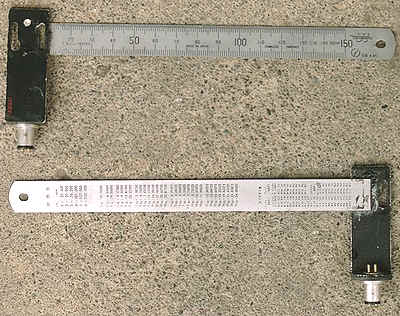
If the arm has SME type shell connector, null point measuring tool as shown in the picture is useful (my personal invention hinted by another amateur). A metal scale (length 15cm) is bonded squarely on the centre of spare shell at mostly used distance 5cm from shell neck: mount this device on arm and swing the arm, read out distance from the centre of shell to spindle when the metal scale is crossing usually twice on the centre of spindle. The figure obtained by this shall indicate null points directly. And the stylus point on the standard shell shall be set to 50mm from shell connector, then two null points alignment is completed. But be careful that arm distance and overhang should be predetermined by original geometry of arm design for the proper setting in this method. Maybe this tool is suitable for checking/measuring null points only. When two null points are measured with this tool, the intermediate value indicates LINEAR OFFSET= (null point 1+null point 2)/2. It is easier to measure linear offset than offset angle of arm. Offset angle can be calculated from ASIN(Linear Offset divided by Effective length).
The usage of every alignment tool is limited by the stages of setting specific arm or the purpose of design target : overhang alignment or one null point confirmation might be enough for pre-mounted arm at system player which has potentially two null points, mounting anew an arm with unknown geometry, transforming the original geometry of manufactured arm forcibly to the fixed design of geometry by skewing the cartridge on shell and so on. Users are often mixing up arm design geometry (as predestined by linear offset design) with its alignment (pivot location=arm distance from turntable centre, overhang or effective length adjustment after pivot is fixed). When cartridge angle is not mounted square on shell, it shall mean that user is changing original design of linear offset to user's optional and sometimes reasonable linear offsets. "Whether it is reasonable or not" can be judged in accordance with the purpose of adjustment or arm design per record diameter to be played on. Funny enough longer arms with same null points suitable for 12inch records are still produced today. Meanwhile we have no intention to play transcription or sound track record diameter more than 12inches. For playing large diameter transcriptions, the null points of longer arms should be designed different from those of shorter arms. We forgot the history of longer arms and their reason (raison d'etre) . Audiophiles are often fond of well-established vintages and/or magnetised by some professional-looking products without essential reason.
Longer arms have potentially less lateral angle error, but in actual performance and alignment, the maximum distortion difference due to arm length is almost negligible. Overhang or offset angle adjustment is more important in practice to obtain lowest distortion. Please also note that the difference of distortion between Baerwald and Stevenson types is also negligible as far as each arm is designed and aligned properly: alignment should be adjusted as per the geometrical design of arm. The following graphs show maximum distortions (%) due to alignment errors. Conditions in this simulation: 1) the range of groove radii to be played on is 146-60mm, 2) signal velocity 10cm/s, 3) effective lateral length from stylus to arm pivot is unchanged i.e., the relation between overhang over spindle and arm distance from spindle to arm pivot is adjusted by shifting whole arm on the bedplate, and 4) the angle adjustment if any is carried out on the slotted holes on headshell.
Distortion due to lateral tracking angle error is relative to groove radius r, signal velocity v and tracking error angle A and groove velocity V: 2nd harmonic distortion=v*TAN(A)/V [v:signal velocity, A:error in radian, V=pi*r*RPM/30]. A book by JVC (1979) indicated as under (d=overhang, lateral tracking angle δ on ordinate). The alpha in lower drawing shows relative distortion rate weighted by groove radius. When maximum angle error at outmost groove is 3degrees, then the value alpha is calculated as 3degrees/150mm=maximum 0.02degrees per mm. When three weighted peak distortions at inmost/mid/outmost groove are of same rate, then the distortion over whole groove radii can be kept "almost" at the lowest as Loefgren and Baerwald had proposed in SP era. But actually it is still questionable whether it is possible or not to make both the angle of Line A to B and the angle of Line C to B at "exact" same rate. Loefgren/Baerwald and others sought solution to make these values "almost" same. I am still wondering whether there can be some optimum or "mystic numbers" about specific arm length and specific groove range making "exact" same value of weighted distortion on three points.