As per BS 1928-1965 (same as IEC98-1964): 4.3.2.1 Nature of groove. ....The reproducing stylus tip motion
shall be tangent to or lie in a plane through the stylus tip and the record
centre, preferably inclined at an angle of about 15degrees clockwise to the
normal to the record surface through the stylus tip, as viewed from the record
centre. NOTE. In practice, angles of between 0 and 25 degrees may be encountered.
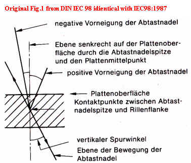
Fig. 1 from IEC98-1987 shows VTA as an angle
of 20-25degrees anticlockwise to the normal to the record surface through the stylus
tip as viewed towards the record centre.
Note on
my drawing: In original IEC fig.1, tip was in the groove and not on the record
surface. Any cantilever shall be long enough as compared with groove depth.
Popular static 'VTA' is approximation while IEC defined VTA as tip
motion plane during playback. I suspect it is not single plane, but
swaying planes actually - see Measuring Methods of VTA.
My comment on SRA: IEC98-1987 clause 8.1 recommends a stylus rake angle (SRA) of between 0 and -5degrees as optimum for reproducing styli while clause 11.3.3 (non spherical styli) allows +4 and -8 degrees for SRA. VTA/VMA was not stipulated for stereo groove earlier than 1963. In the same way, SRA of the special form needle was discussed only after 1980. Analog is always fuzzy like pudding - you can see how some standards are made after representative products at the time.
The outlines of VTA & SRA
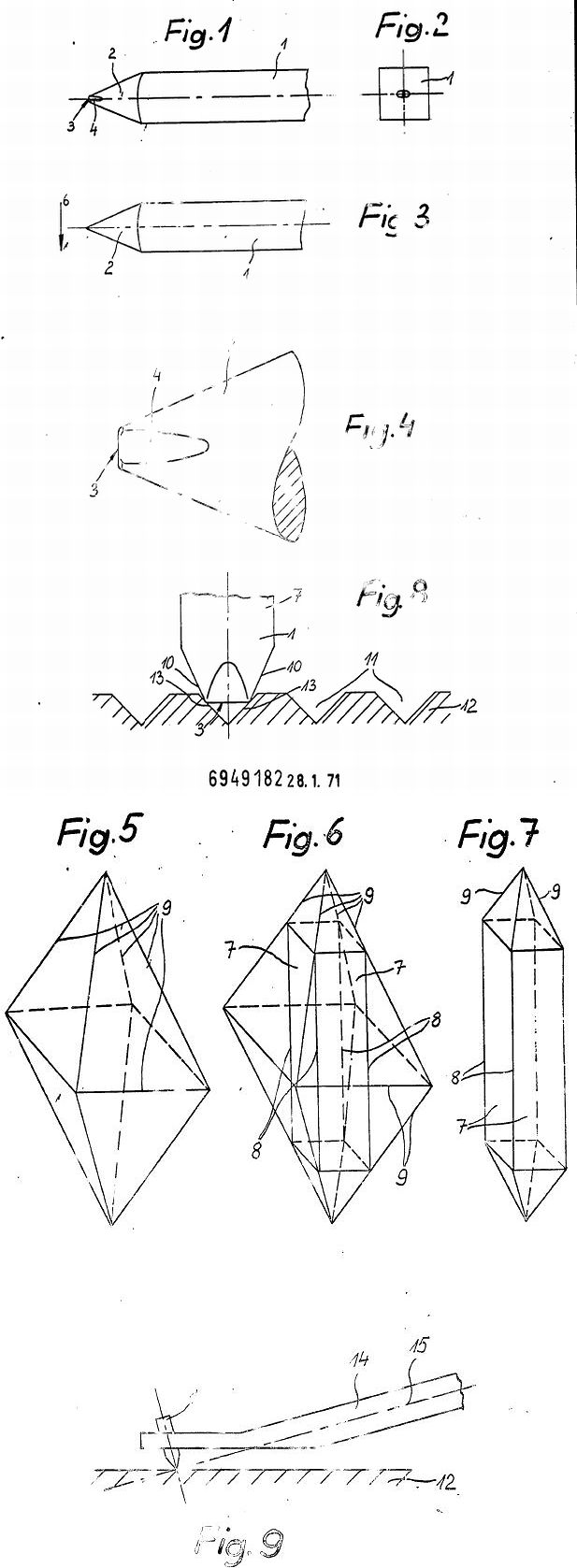
SRA should be measured by the vertical contact line on groove walls. But its measurement is difficult from looking the profile of special formed stylus. The following drawings are taken from US patent application by GYGER. Here SRA 0 degree is kept diagrammatically in spite of various line contact styli: Fig.4-5 for styli are corresponding to Fig No.8, Fig.6-7 to Fig.9, Fig.10 to Fig.11. Usually other line contact styli have rather obscure profiles.
VTA and SRA can be changed with VTF. The following calculation is based on static vertical compliance. As per IEC98-1987(11.3.3 Stylus Rake for non-spherical styli): The stylus rake in the direction of groove travel shall lie between +4 and -8degrees when playing at the tracking force recommended by the manufacturer. This should be taken as allowance while optimum rake angle is between 0 and -5degrees as per clause 8.1. I suspect that the correct mounting of spherical tip on cantilever is easy without mentioning while actual stylus assembly at mounting special stylus on cantilever is often evading from nominal angles. Once Mr. Shibata commented about his invented SHIBATA stylus tip: "Care should be taken on the inclination of tip at normal usage but its tolerance is about 5 degrees in all directions. So it is not too particularly severe compared with 7 degrees tolerance for elliptic tip and 10 degrees tolerance for spherical tip." - I interpret this as disclosure at manufacturing side for mounting styli, and not as warning to end user. It is often said that spherical tip has two round contacts on groove walls so that its inclination up to 10 degrees has no harm, whereas line contact tip has vertical oblong contacts on groove so that its tolerance is narrow.
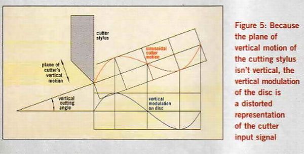
The following graph shows the displacement images of
stylus with
VTA variations when tracing on sinusoidal vertical modulated groove. This
drawing is originally made for lateral tracking error. When this drawing is seen
from horizontal level, then this drawing can show the relation between VMA and VTA. y(VTA=VMA),
y'(VTA<VMA) and y"(VTA>VMA).
The nature of this second harmonic distortion is same as that of lateral tracking error. The difference if any from lateral tracking error shall be:
this distortion in effect is varying in accordance with (not only groove radius
and recorded velocity, but also) the inclination of wave forms modulated in
groove because the spring back action of lacquer is non-linear and VMA in
effect shall vary according to the momentary inclination of wave forms (hence
VMA in actual record is not one and same throughout). Better
forget about this complicated VTA/VMA matter! Nevertheless (Trotzdem)
I enjoy vinyl. During making this simulation I understand why distortion due to
tracking angle error is not easily audible. This distortion is eminent at the
high velocity level and inner groove radius. Its distortion is usually inaudible
at the lower recorded level than 5cm/s and angle difference less than 10 degrees
[estimated maximum distortion around 4.2% at groove radius 6cm]. To attain the distortion indicated as following graph having parameters
for instance : Displacement (amplitude) 25 micron, Frequency of modulation 1000
cycle/sec, Velocity 2*pi*f*amplitude =15.7 cm/sec, Groove Radius 5.75cm, VTA
difference 0.4 radian=22.9degree and 2nd harmonic distortion 33.1% as calculated
with usual equation [ (v*TAN(A)/V) where A is error angle in radian: v velocity
: V groove line speed] or 42% if peak velocity of distortion component (y'-y or
y"-y) having double cycle mainly is compared to the velocity of
fundamental undistorted sine wave (y).
[My Note on the displacement image of stylus
between VMA and VTA. The relation between signal and VMA is shown in a
diagrammatical drawing in Hi-FiNews February 2004 by Keith Howard. By
tracing on such deformed wave by cartridge with corresponding VTA, original
signal wave of input is restored.]
Do not care much about VTA and Lateral Tracking Angle errors since vinyl distortions from other factors are of higher grade. Consultants of Shure Brothers experimented and reported (Psychoacoustics, the Determining Factor in Stereo Disc Distortion JAES Volume 12 Issue 2 pp. 115-123; April 1964): "It was determined that even when the tracking angle error is reduced to zero, the distortion products remaining are, by established standards, unreasonably high. Listener tests conducted under carefully controlled conditions indicate that the ear and nervous system will effectively reject these remaining distortion products."
Mr. Yamamoto after calculating and explaining all distortions, said in his book (1971) clause. 2.4.4(3) :"Is vertical tracking angle error distortion (VtD) audible? It depends on program source. At inner grooves, tracing distortions are larger and VtD is masked by them. VtD is affected only by the vertical component so that VtD is moderated at usual music containing larger part of horizontal component. Therefore VtD is not disturbing when sound image is narrow as in chamber music or solo, whereas VtD can be audible at light music or matrix 4 channel records which contain considerable vertical component."
The following tables are based on Japanese reference book "Record Player" (1971) by Mr. Yamamoto who reported VTA as follows: I think his measuring method was based on test record (geometric structure of Decca was said as 0degree while he measured 12 degrees).
| VTA of cartridges in early '60s | |||
| Sample | Make | Model | VTA(degree) |
| 1 | Neumann | DST1212 | 8 |
| 2 | Decca | ffss | 12 |
| 3 | Elac | SNM106 | 15 |
| 4 | Shure | M44 | 16 |
| 5 | Dual | 1007A | 18 |
| 6 | ADC | ADC-1 | 22 |
| 7 | Ortofon | ? | 22 |
| 8 | Fairchild | SM2 | 26 |
| 9 | Shure | M33 | 28 |
| 10 | ADC | ADC-2 | 30 |
| 11 | Empire | 88 | 32 |
| 12 | Pickering | ? | 34 |
| 13 | Shure | M77 | 36 |
| Average: | 23.0 | ||
| VTA of cartridges around 1970 | |||
| Sample | Make | Model | VTA (degree) |
| 1 | Satin | M-11E | 16 |
| 2 | Audio Technica | VM-3 | 18 |
| 3 | Denon(Columbia) | DL-107 | 18 |
| 4 | Technics(National) | 200c | 20 |
| 5 | Ortofon | SL-15 | 20 |
| 6 | Toshiba | C-100P | 22 |
| 7 | Fidelity Research | FR-5 | 22 |
| 8 | ADC | 220 | 22 |
| 9 | Grace | F-8M | 26 |
| 10 | Supex | SD-801 | 26 |
| 11 | Micro | M-2100/e | 30 |
|
Average: |
21.8 | ||
| Supplementary and /or alternative data in the measured frequency and crosstalk charts | ||
| Shure | V-15Type II (1967) | 23 |
| Denon | DL-107 (1969) | 17 |
| Audio Technica | AT-35X (1967) | 17.5 |
| ADC | 10/E MKII | 19 |
| Pickering | 999VE | 21 |
| Satin | M-11E | 13 |
| Stax | CP-X (1970) | 15 |
Average is similar but variation range of VTA is narrowed after '70s. I will add the following table to above in order to show that variation range of VTA is further narrowed. The data of VTA are taken from catalogues and/or my approximate measurements. It is quite unsure that some longtime selling models have not changed their VTA for these three decades. Ortofon SPU Classic series reissued after 1987 are said to have VTA 20degrees while old SPUs in '70s were said to have VTA 15degrees nominally. I suspect that many manufacturers have been adjusting the nominal data in accordance with standard of each time without any essential change in product since the quality control of VTA especially for high compliance cartridges is very difficult.
| My collection of Cartridges since 1975 | ||
| Make | Model | VTA approx. in degrees |
| Audio-Technica | AT33PTG | 23 |
| AT150 | 23 | |
| DENON | DL-110 | 20 |
| DL-103 | 16 | |
| Dynavector | DV-50A | 20 |
| Karat 19R | 20 | |
| FR | FR-6SE | 18 |
| GRACE | F-8L'10 | 23 |
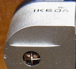
| IKEDA | 9CV | 20 |
| ADC | XLM II improved | 20? |
| ELAC | STS455E | 20 |
| Goldring | Eroica GX | 20 |
| Ortofon | MC-20 SII | 20 |
| Pickering | XV15/625E | 22 |
| Shure | V-15 III | 15? |
|
AVERAGE: |
20 degrees | |
Sometimes deviation of +/-5 degrees from nominal VTA might be found in actual products. In case of EMT stereophonic cartridges around 1997, VTA 18 or 23degrees (each with allowance +/-3degrees) was selectable on demand. Interestingly I find the following passage in the export catalog [August 1973] of Neumann SX-74 cutter head : "...the cutter was constructed to cut an 18°angle when correctly mounted. Lacquer springback is included in this calculation." This shall mean that cutter head angle is more than 18degrees and the vertical angle (VMA) recorded is around 18degrees compromising between old standard 15degrees and then current standard 20degrees+/-5 (BS1928 in 1972).
Various devices to change VTA drastically and effectively have been invented: for instance headshell or cartridge incorporated with adjustable VTA (some of Perpetuum-Ebner headshell & ADC cartridge as shown in US patents). They are theoretically good but practically nonsense since nobody can fix correct VTA for every cartridge whose VTA in actual production and practice is deviating from nominal value. Please note that true horizontal level at user end is not easily attained and that an additional flexible joint at shell may invite resonances due to mechanical weakness at joint. Also note that an invention by Hagenah for PE was originally intended to compensate the height difference between the first playing record and the last playing record in automatic record changers [the height of the stack of records more than 20mm - which was no problem for monaural records, but deviating from then current standard tracking angle 15degrees for stereo records].
There was an interesting patent in this connection (US patent
3538266 invented by Cho and assigned to Micro Seiki and embodied in their IM type
cartridges VF-3100/5 & VF-3100/e around 1968). Unique stylus holder knob was
intended for optimum stylus pressure. It is explained as follows:
"In this position (Fig.7) the stylus pressure against the record 74 is
zero (0) and the damper is, not being in the neutral position, deformed. The
stylus pressure is progressively increased until the forward end of projection
68 reaches the surface of the record 74 as shown in Fig. 8. The projection 68 is
preliminarily adjusted in length so that the stylus pressure is of optimum value
when the pickup cartridge is in its position as shown in Fig. 8. In this
position, the axis of the armature 64 is parallel with the tubular guard and is coincident with the axis
of the magnetic pole of the magnet 58. The damper 73 is, thus, not deformed and
is its neutral position, assuring that the armature 64 is precisely oscillated
according to mechanical oscillation of the stylus 66. After completing the
operation for increasing the stylus pressure, the bridge 70 is turned upwardly
about the axle 69 into a recess 75 in the housing 50. Reproduction operation of
the record 74 is then carried out in this state. "
This device might be useful for obtaining optimum stylus pressure enabling the armature to set in the
neutral position for linear
push-pull action. Why this device is not adopted in later models? I suspect that
the damper itself tends to change with the lapse of time and temperature so that
the preliminary designed position (i.e. VTA for cantilever) does not
always coincide with
the required value of stylus pressure in practice. VTA is one thing,
Trackability with due stylus pressure is another thing, Distortion is again
another matter involved - and the users spin their reviews.
Three representative shapes of damper each applied
on MC, MM and X'tal as per
Yamamoto showing dampers deformed by pressure (exaggerated).

Fig. 3.95 shows excessive VTF while Fig. 3.96 shows VTF zero for high compliance cartridges. Magnet or armature should have central position under normal VTF as shown by Micro's Fig. 8 & 9 though the cranked shape of cantilever is now obsolete, once popular due to wide clearance between cantilever and upper side of sheath. When magnet or armature is shifted from central position then cross-talk and sensibility are affected worse.

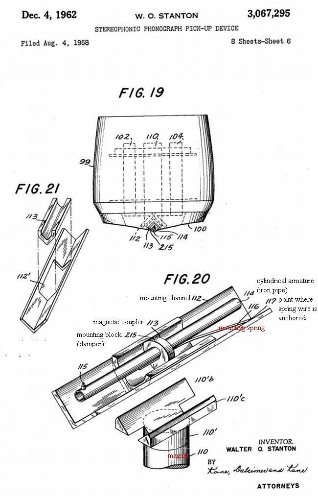
Vertical compliance is lower than lateral compliance generally because of compression of damper by VTF or stylus tracing method. Other forms of damper are invented and applied for some cartridges. For example, uneven stiffness or thickness between upper side and down side, double dampers and protruding point at upper side having selective stiffness etc. To avoid stylus moving forward, suspension wire is conneced from magnet or armature to stylus sheath: This is not Shure's invention but Stanton's US patent 3067295 & 3146319 etc.
The following drawings are taken from US patent papers by B.B. Bauer assigned to CBS. Angle A is cutter angle, S is springback angle and B is recorded angle as a result. B (VMA: effective vertical modulated angle)= A-S. Fig. 4A shows an inserted wedge for cutter compensating the springback value.
According to Mr. Yamamoto (1971):
CBS laboratory reported springback effect at lacquer recording - the effective vertical
modulation angle was much smaller than cutter angle. American recording companies CBS & RCA used cutter angle 23degrees while European companies such as London/Decca used 0 degree. As a result VMA became 0 for CBS/RCA and -10degree for London/Decca. At that time the manufacturers of
cartridges were
perplexed how to set their VTA for their stereophonic cartridges. IEC/RIAA recommended standardisation of VMA to 15degrees so that
SPU/EMT/Shure at the time adopted VTA as 15degrees. Cutter angle was adjusted to achieve VMA 15degrees by inclining cutter angle further. In case of
Westrex, original cutter angle was 23degrees and its VMA became 0-1 degree due
to springback of 22 to 23degrees. Hence additional wedge of 14degrees was inserted
to achieve VMA 15degrees as a result. [My additional Note: All cutting faces of lacquer cutting styli are made
upright as shown in above Fig. 4A/4B/4C - the mounting angle of cutting stylus
must be arranged in accordance with respective cutterhead angle]
Mr. Howard also wrote in HFN 2/2004 about VTA/VMA and told same history. There
Mr. Howard made an interesting summary about VMA of actual records as follows
(besides possible VTA variation of actual cartridges: from 18 to
30degrees) :
1) No record has a single
well-defined slant angle - it is signal-dependent and also varies with the
position across the record surface.
2)The variability in average slant angle
across any but the most meagre record collection is likely to be anything up to
5 degrees even with modern LPs, and even larger with older pressings.
Mr.
F.L. Capps in his US patent 2187512-1940 (recording stylus) commented: "during
a recording operation the cutting face of the stylus is at an angle or 90
degrees to the surface of the blank being engraved or cut, although the 90degree
angle may be varied approximately 5 degrees forward or backward."
Such was the vinyl production that it is of no use to apply unique tweaks
afterwards.
In case of DMM (Direct Metal Mastering) method by TELDEC, both
SRA (inclined edge angle) & VMA (around 5 degrees) of the cutting stylus
for copper layered disc are arranged quite different from lacquer cutting
because copper disc is hard without springback effect and heated stylus method
is not applicable. See the details in my another page in
Japanese. Mechanical VMA 5 degrees structure was compensated beforehand by
electronically processed input signals in order to play back the vinyl record
suitably with conventional cartridges having VTA around 20 degrees. Klemp &
Redlich reported in JAES(April
1965)"A New Method of Disc Recording for Reproduction with Reduced
Distortion: The Tracing Simulator" and mentioned: "By
means of an analog-computer technique, geometric playback distortions are
simulated during disc recording. Second- and third-order harmonics are recorded
so that the vertical and lateral components are free of tracing distortion in
playback and pinch-effect distortion is removed in lateral recording. The method
also offers the possibility of correcting the vertical recording angle by
electrical means." The underlined part was realised
officially in
DMM method as described in US patent 4538256-1985. But then what has become of
SRA issue for DMM method? Has TELDEC recommended spherical stylus instead of
line contact stylus for DMM records? In this connection I introduce two
patent papers about reproducing styli having queer SRA. Mr. Tsukamoto (the
founder of SATIN) in his Japanese patent paper S52-63702(1977)
mentioned that the SRA from +3 degrees to +10 degrees is optimum which is known
by his experiments. On the other hand Mr. Weinz (Weinz-WEKA) in his German
patent paper 6949182(Fig.9)introduced a
radical minus vale of SRA in order to maintain strength of stylus as in case of
DMM arrangement.
Interesting report is found at "The BAS Speaker" (the
Boston Audio Society's newsletter) Volume 8, Number 4, January 1980 (P.31):
The question is complicated by the
uncertainties in the technique of measurement. The conventional RCA and DIN test
records can yield measured vertical tracking angles as much as 5 degrees higher
than those obtained using either the geometrical method or the CBS STR-160 test record. According to Shure
Brothers,
"a variation of approximately 3 degrees is obtained from two different test
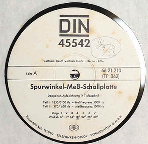
bands on the DIN 45542 test records."
Their comment refers to the measured variations of VTA on DIN test record (complex tones of
1850Hz+3150Hz & 370Hz+630Hz). J.G. Woodward of RCA Laboratories around 1963-1965 worked vigorously
on this subject (esp. FIM measurement using 400Hz+4000Hz tones recorded
at a 4:1 velocity ratio):
"Techniques for Measuring the Vertical Tracking Angle of Stereophonic
Phonograph Pickups" JAES July 1965 with summary "The record contains
bands having vertical recorded angles between -12° and +44° in 4° increments.
A second group of bands contains angles between 7.5° and 25° in 2.5°
increments to permit more careful measurements in the vicinity of the standard
15° angle." BAS experimenters used similar RCA record. CBS STR-160 recorded 400Hz signals with VMA from -6 degree to 43degrees
(15 steps) and its measuring method as I
understand is: 1. Pick up differential output
from two channels 2. Measure the value of 2nd harmonic
distortion through band pass filter. 3. The lowest distortion
at specific VMA of a band should indicate corresponding VTA of a cartridge.
Following example of measurement is taken from a book by JVC(1979) engineers who
proposed another method since CBS test records were discontinued to be produced.
This method is based on geometric view though this
method has some drawbacks: 1. The microscope must have extra long focus
distance 2. The cantilever length must be known beforehand or
pivot fulcrum location can be seen - then nobody but maker can measure it
before assembly! 3. Parallax from
observing point must be compensated (by triangulation?) since actual vertical tracking angle
(dynamic VTA at playing) is little
different from observed angle (static VTA). Every test records (RCA/DIN/CBS) seem to
have different modulations (frequencies/amplitude/vertical or 45degrees etc) and
different radii of recorded bands so
that the measured data can be different. Current
valid IEC(1987) recommends VTA/VMA 20-25degrees for both records and cartridges,
but does not indicate any definitive measuring method for VTA/VMA (any specific
test record with 20-25degrees VMA has not been arranged officially as of today).
In fact, VTA was described in Art. 8 (The groove) of IEC98-1987 while
it was not touched in other places (Art.11 reproducing equipment, Art.12
specifications to be shown by maker for the reproducing equipment, Art.13 conditions of measurements,
Art.14 measuring methods).
DIN 45542(1969) Test Record Side A for testing VTA. I suspect that the recording source of pre-deformed waves based on simulations (tracing simulator adding the reverse signal of the expected distorted tracing wave) was arranged by TELDEC as experiment before aforemsentioned DMM method and then cut into record without changing cutting angles actually. The Side B (Intermodulation-Mess-Schallplatte) commentated that this record is distributed by Beuth Verlag, recorded by DG and produced by TELDEC. Also note that ring No.4 for VMA 18 degrees is recorded in the middle of total 7 rings on Side A. This record together with other test records was given free to me recently since nobody other than me may be interested in these test records. It is lucky though it is bothering me to measure cartridges with this test record now.
There is US patent #4752921(1988) invented by (Dual-)Thomson engineer about "Record player with means for capturing recording and scanning angle" which I assume to be connected with VTA shell equipped on Dual CS5000, but the most important point of this invention (effective measurement of VMA/VTA on record and cartridge) has not been realised. The value and effect of "springback" on recording materials are not mentioned. Thus again vertical angles among cutter and record and cartridge remain fuzzy. Funny enough every patent claimer would tell his own/new story.
Please look into the CBS's US patent 4359768(1982) about
vertical tracking angle meter and take notice of Fig.2: AVERAGE POSITION OF DYNAMIC
PIVOT POINT showing meaningfully the large value of dynamic VTA than that of
static one. The engineers of Shure Brothers commented in Phonograph
Reproduction 1978: part II published in AUDIO/June 1978 as follows : "Although
a universal standard VTA for the cutting and records does not exist. we do
specify the geometrical tracking angle of the cartridge. This is to be
distinguished from the effective VTA during playback. The latter must be
determined by a suitable test record". disclosing
further "V15 Type IV was designed not to exceed 23degrees to insure that it
will meet the DIN specification of 20+/-5 degrees"). This
23degrees is static/geometric figure (maybe at the recommended VTF) while BAS tester indicated more than 28
degrees for Shure V15 type II/III/IV. In this context I can understand why the CBS patent paper commented:
"the average vertical angle of
ten high quality pickups that were measured in the course of the study was
29degree., with angles of some as small as 22degree. and of others as large as
33degree". If I do not misunderstand, these dynamic figures are larger than static/geometric
measurement of VTA showing that average position of dynamic pivot point is
located higher than static/geometric structure. This means also that arm head
itself is lifted or sunken during playback. Dynamic or effective VTF (pressure to groove
walls) is changing by following reasons : 1) recorded frequency and amplitude
against mechanical impedance of cartridge (thus miss-track can occur on
various parts of wave form: not only downhill part) 2)
scrubbing motion by fluctuating stylus drag force (see the following exaggerated
Fig.2 from Shure's
USP4275888) or stick-slip motion of stylus on groove
3)record warp etc. Thus test record method too is little relevant to actual playback of
various records. IMO: In consideration of narrow range of VTA variance during
playback, low compliance cartridge with relatively heavier VTF can be better than high compliance
cartridge.
Unscientific procedure as I think: a. Cantilever angle at
VTF 0 is decreased after loading VTF on record b. In uphill of
wave, the cantilever is depressed further while arm head with considerable mass
does not move immediately c. In downhill of wave, the depressing
load on tip is made small or released so that effective VTA is to be widened and sometimes
over VTA at VTF 0 because depressed spring can swing back over the natural
position after release. d. Arm head is lifted gradually by the forces accumulated
in the area of uphill or warp. And this is the reason why generally high compliance
cartridge can have higher trackablity (it is different from Hi-Fidelity). I
think the movements of stylus-tip and arm-head have different phase respectively
as CHAOS: stylus+head moves jointedly in very slow speed of turntable >stylus
and head move in different phase respectively in normal speed of turntable > head keeps certain lifted
position while stylus is just touching on the top of undulation in very high speed
as a hydrofoil-ship. Am I crazy? Percy Wilson in THE GRAMOPHONE HANDBOOK (1957)
P.103: 7.31 Groove Amplitude and Curvature: "Mr. Watts has now been able to
set up apparatus by which these photographs were taken in such a way that the
actual tracking of the stylus in the groove can be observed whilst the record is
being played. He reports that on occasions the stylus appears to be floating,
without touching the walls on either side! Yet the ear does not detect anything
different". Now I feel that neither dynamic VTA
(changing by recorded groove) nor static
VTA at recommended VTF is valid and that only superficial VTA at VTF 0 at the
time of ex-factory can
be definable as figure. Or stop defining VTA in order to avoid
misunderstanding at users who demand simple numbers or handy conclusion (as
Shure stopped indicating compliance of cartridges since late 1970s in the course
of their studies. Meanwhile some snobby amateurs would try to
calculate low-frequency-resonance based on some given figures of compliance
without thinking why 10 Hz or around is optimum).
Obscurity about VMA/VTA/SRA issues (almost past as vinyl
itself).
I don't know any real reason why SRA for reproducing stylus is not straight up
while almost all cutting faces of lacquer cutting styli are made upright. Maybe -2degree
as optimum SRA is concerned with the elasticity of vinyl when tracing with
VTF (vinyl deformation) - some persons claim different SRAs such as +3~+10 to be
optimum for some records. Then it shall depend on the material of vinyl (hard or soft).
It is impossible to make negative degree of VTA for cartridges. Then early stereophonic records
have never been played back
properly. Meanwhile it is incredible that the material of
lacquer and its elasticity is unchanged. I assume that improved lacquer materials
should have smaller
springback (for example 5 degrees only) and that normal pressings after '70s should have VMA as designed
between 15 and 25degrees. I find a following passage in a JVC book (1979) P.168:
"Cutter
angle shall change with the conditions of cuttings such as type
of lacquer disc etc. When condition changes, the test record for measuring VMA
by cutting rectangular signal (triangle as groove form) is produced and
cutter angle is adjusted to reach specified value of VMA. .... Since 1960s (stereophonic era) VMA 15-20degrees was
standardised.
Once IEC specified 15degrees but recently revised VMA to 15-25degrees in
accordance with the tendency of the recent produced cartridges".
And now since DIN45547(1981) and IEC98(1987) VMA is again revised to
20-25degrees from previous 15-25degrees.
I could not find the reason why VMA/VTA standards were changed by time (advance of cutting technology or trend of cartridges as mentioned above). Why VMA 15 dgrees at first? Walton explained in Wireless World/Dec. 1967 (P.583):”Much of the work on the 15 vertical angle question still remains little publicised, and it is this work that uncovered such phenomena as master record groove and record cutter spring back which made it necessary to move a cutter at one angle while its vertical orientation remains at another. Since this effect varies with frequency it means that the back angle of cutter is effectively increased at some frequencies with resulting limitation on the maximum recordable velocity." < further commenting on shearing damage on recording material> "an effect [blemish] apparently depending upon cutting velocity, though on the leading rather than the trailing slope of the modulated groove wall. This effect is absent where velocities are such that the angle between the instantaneous direction of the groove and normal general direction of the groove is less than about 25 degrees. The effect also seems to produce severe damage to the groove formation where this angle reaches about 40 degrees. But until all the factors are calculable on different cutters, the practical measurement will probably be best available guide as given on a test record." I assume: The instantaneous maximum direction of cutting angle is total of maximum sinusoidal As(inclination on groove formation due to signal) and cutter angle. And maximum angle of groove formation just after passing cutting stylus=As(Max)+VMA(=cutter angle-springback). I feel that springback effect is not explained enough as of today.
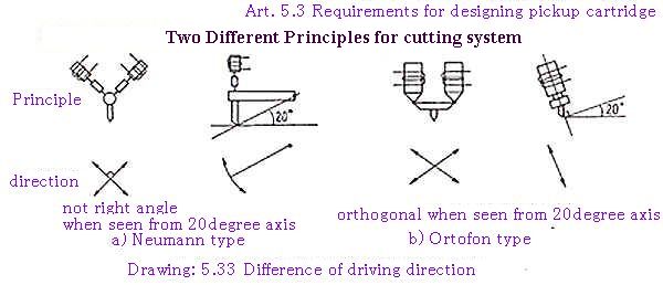
There is difference in the cutter structure between Neumann type (better to say Westrex type) and Ortofon type. JVC book (1979) P.205 indicated the following drawing 5.33 and explained as follows: "When a cartridge is designed based on one of the principles, there arises a difference of crosstalk. But this difference as calculated is around -30dB so that it is no real harm."
| Angle (degrees) | Crosstalk (dB) |
| 10 | 15.2 |
| 5 | 21.2 |
| 2 | 29.1 |
| 1 | 35.2 |
| 0.5 | 41.2 |
MY CALCULATION
When an
isosceles right triangle is inclined 20 degrees, its height is reduced to 94 %
Included (apex) angle of triangle 93.56 degrees [=2*atan(1/0.94)]
Difference to 45 degrees 1.78 degrees [=93.56/2-45]. 20log(tan
1.78degree)=-30.15dB
See details on my
distortions.xls (First Sheet Distortion J: The reasons of crosstalk at cartridge)
My funny proposal for the reformation
of Neumann/Westrex cutter
If driving coils (directions) for cutter are
arranged to cross at 86.44 degrees instead of conventional 90 degrees
then this crosstalk will not arise for usual
cartridge with VTA 20 degrees.
In case of an isosceles triangle with apex
86.44 degrees: Its apex becomes 90 degrees as seen from 20 degrees axis.
EQUATION to get reformed apex angle =
2*DEGREES(ATAN(COS(VTA)))
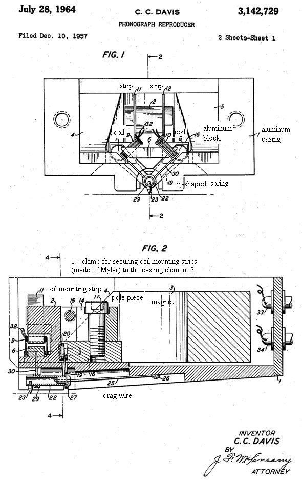
This is concerned with the historical development of stereophonic recording i.e., 90 degrees writing systems (trial by Lateral/Vertical=0/90 system and then standardised 45/-45 system). The traditional perpendicular plane of driving the cutter has not been touching the VMA/VTA issue originally while usual stereophonic cartridges follow the sensing direction on inclined plane generally. Cartridges based on Westrex/Neumann principle were old or rare MC systems such as Westrex 10A, Neumann DST and Ikeda (Westrex and Ikeda having almost upright coils based on perpendicular plane). These sensing points were located above or near stylus and not at the end of cantilever. Neumann DST & Westrex 10A had smallest VTA sticking to normal plane in mind eliminating VTA issue (these were products before the stipulation of VMA/VTA). The moving coils of Ikeda are upright while VTA around 20 degrees is obtained by tension threads. I remember that Mr. Tsukamoto of SATIN pointed out in early 1970s:"Recent stereophonic cartridges are not based on the original principle of Westrex/Neumann cutter since these cartridges have sensing points tangent to VTA line or cantilever." Also note that the vertical modulation amplitude is less than 50 microns (0 to peaks) or 0.5 degrees as seen from fulcrum so that these driving structures (directions) remain different each other. However, average separation of cartridge is less than 20 dB for full frequency range so that this threshold (-30dB due to the difference of structure) does not matter actually. The highest separation is obtained usually at mid-frequencies (1kHz-6kHz in resistance controlled domain) for cartrige so that separation at 1kHz is indicated as specification or representative value though this is again kind of big numbers (brag or bluff) one would like. My question (mess): Some cartridges indicate crosstalk more than -30 dB at some limited frequecies range (1.5kHz-4kHz) according to Yamamoto(1971) using CBS test record STR-100 Band 1A(left channel modulation) & 2A(right channel modulation). JVC(1979) measured a hundred cartridges showing some cartriges' separation more than -35 dB at some frequecies in contradiction to their diagram about structure. Then the difference of structure is imaginary matter since springback effect on recording complicates the geometric situations further.
My drawing illustrating two different planes having each rectanglar coordinates
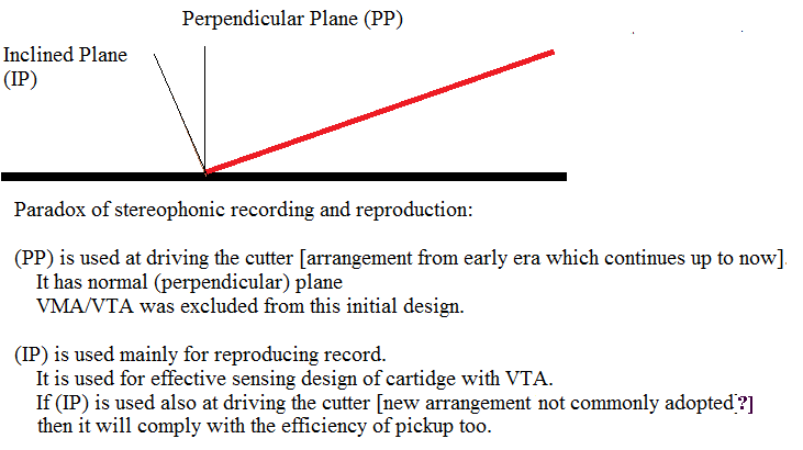
The expression in IEC98(1964) &BS1928(1965) about VTA (The reproducing stylus tip motion shall be tangent to or lie in a plane through the stylus tip and the record centre, preferably inclined at an angle of about 15 degrees...) has puzzled me for a long time. But it is understandable in the context of above drawing. Meanwhile it is unclear whether springback effect on lacquer can be different between Neumann and Ortofon cutters or not. I think that Westrex/Neumann's cutting direction (driving downward) had some merits regarding engraving the resistive recording materials since TELDEC's DMM cutting method also adopted similar structure. See also structure of Westrex 3D cutting system.
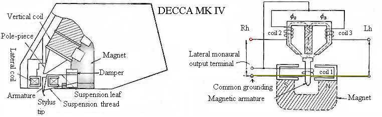
In connection with above, I find that superficial cantilever angle is not always equal to VTA. In fact, VTA is also concerned with the effective sensing arrangement of generating system as shown in my following drawing for Decca cartridges claiming on "positive scanning". Its vertical sensing point (i.e., armature of magnetic piece) and its sensing direction (i.e., vertical coil wound on the extension of pole piece) are not known from appearance - its true VTA is different from tension thread angle and cantilever angle (some old documents indicated VTA 0 degree for early ffss maybe from structure or appearance while Yamamoto measured 12 degrees). An explanation on drawing. When the armature is extended to H position, then the pole piece and coil angle must be inclined or when the end of armature is located at L position, then the pole piece and coil angle must be arranged vertical. Otherwise, effective VTA is not equal to cantilever angle. Once I imagined these pole piece angles were corresponding to VTA, but both angles can be valid and having same effect when the armature extension is designed correspondingly. I find two drawings for Decca: vertical pole piece (old patent paper) and inclined pole piece (MK4) but could not know the effective location of armature. The real magnetic circuit cannot be known from diagrammatic drawings or appearance because the magnetic flux flows not straightforward (usually arc) and the armature has considerable volume or length (not a single point as shown diagrammatically). Same can be said about legendary Neumann DST (Elektrodynamischer Stereo Tonabnehmer) having much obscure magnetic circuit. Its stereophonic generating system cannot be understood without arc magnetic flux in repellent magnetic fields produced by two magnets.

Arm height adjustment is not VTA adjustment in strict definition. The term "VTA" should be applied for cartridge proper in stereophonic use: i.e. against vertical component of modulation.
The object of height adjustment at arm is simply to make cartridge mounting face parallel to record/turntable (the height of cartridge body is ranging usually between 15-20mm). Height adjustment +/-5mm with same VTF cannot change effective VTA/SRA on cartridge essentially (for example: max +/-1.3degrees at lateral effective length of arm 220mm). Meanwhile there is a funny tweak term "Tail down or up" of arm as often called by amateurs. Its geometric and dynamic difference if any might be a matter of static balancing arm (VTF by shifting counter weight) and not the cartridge nor record.
What is apparent from above construction (when VTF is adjusted at horizontal level of wand and then the height of arm is changed at arm base so that the rear counterweight shaft and front wand are inclined from horizontal level): Effective VTF shall increase for tail down while VTF shall decrease for tail up according to the relation among pivot and center of gravity each for counter weight and pickup head (position g is rotated on axis p by tail up or tail down). I will not deny the effect of uneven height adjustments on some arms (so-called sweet spot esp. for knife-edge pivots). I think its cause is not VTA nor SRA because such adjustment is to improve the playback of monophonic record too. Height adjustment and lateral balance adjustment for some arms affect pivot location or pressure balance on bearings for vertical movement so that it tends to cause bearing chatter during playing records: one side of pivots would lose stable contact with bearing.
There is another design of arm as under. I think the following explanation by AT is tricky (i.e., ignoring the compliance of cartridge). The stylus drag force is relayed to cantilever fulcrum of cartridge via stylus tip so that the resilience of elastic damper at cantilever fulcrum will make arm wand to move irrespective of arm pivot height difference. Anyway the fact is not so simple: the cartridge compliance and the effective mass of arm system and the kinds of forces (frequency and amplitude) from the groove should be involved in determining which one (stylus tip or arm wand) starts lifting. IMO: this pseudo-modern style of bearing location began from LEAK Stereo Pickup in early 1960's.
VTA is much more than the inclined angle of stylus-(arm)pivot line from horizontal level. The vector of frictional force between stylus and groove is directed on horizontal level. The following table is based on my pseudo-science since it is based only on the coefficient of stylus drag between tip and record. The stylus drag forces are never constant.
| In many arm designs, stylus point or tip is located around 15mm lower than arm pivot level. Parameters: the stylus drag coefficient "α" between tip and record as 0.3 and if the tip-pivot line is inclined 3.7degrees for example of arm L230mm x H15mm. This inclination angle is called as "θ" in the following drawing. |
| Then estimated tracking force (mass) variation due to this inclination θ 3.7 degrees is only -2% (98%) |
| Meanwhile VTA of cartridge (around 20degrees) is affecting tracking force much more than above: for example 11% [vertical component of stylus drag force = 0.3*TAN(VTA of cartridge) and rotational component of stylus drag force to cantilever=0.3*SIN(VTA of cartridge)] |
Practical considerations (common sense): there is no reliable tweak which can be generally applied on every cartridge/arm.
There are too many variations in the make of tip shape, damper, mechanical/geometric/physical construction of arm/cartridge. Frankly speaking products allowances are much wider and problematic than nominal specification or theoretical calculation (usually happy-go-lucky person wants to believe nominal values or designers' comments without testifying the validity by oneself). Hence I can only suggest some commonplaces as under:
Mount the cartridge top face horizontal when playing the records. There is variation in record thickness (the recorded area). But you have no need to worry about thickness variation since the warp rate of actual records is often more than 0.8mm.
Adjust the downforce of arm at cartridge tip as recommended for a cartridge. The recommended VTF for a cartridge has usually allowance +/-20% from the middle (optimum?) and practically +/-50% can be allowed for some cartridges. Too much deviation from the recommended VTF shall affect sound quality because the generating element (magnet or coil) shall be shifted from the centre of generating system (the location of push-pull linearity). Please imagine what shall occur on speaker (woofer) when amplifier output contains high residual DC voltage more than 0.2V: speaker coils are biased.
AND forget about VTA/SRA/VTF issues and reproducing system itself and enjoy the music as you like - the last is most important. Pudding is made to be eaten, not to be discussed how to eat this way or that way. My motto after all: Don't dig around vinyl matters! Simply hear and enjoy abundant illusions!
When we look into the history of analog records and the status of reproduction, we find that WE HAVE BEEN INSENSIBLE TO DISTORTIONS TO CONSIDERABLE EXTENT. Harmonic distortion from both lateral and vertical tracking angle errors IN CASE OF MUSIC is not audible generally as ascertained by Tollerton's AES paper in 2009. Meanwhile many audio fans fumble with alignment protractors or arm height adjustments, hoping any form of improvement. Often we audiophiles would not admit such insensibility by ourselves and pretend to hear "differences in any form." I think there is occasional difference arising from not auditory nor physical but psychological reason (there is difference, but no better sound actually). Someone said such bias in our heads corresponds with the degree of efforts and perspiration - I could not retort on his saying. Some kind of distortion is tasted sweet surely (such as springy sound on float suspension for belt-driven turntable or IM distortion/thick bass tones some Japanese would like by using heavy arm head system) and one would like one equipment or another not because of physical hi-fidelity but because of his taste. Reverse polarity of both channels could not be heard as difference usually but audiophiles on their arm chairs would not admit such fact. Recently I find a discussion about some CD players having reverse polarities between recorded CD and playback.
Audio maniacs are really fond of tweaks or adjustments in expectance of improving sound quality as if they feel itch to do something on their audio equipments. Esp. novice after reading some audio magazines is tempted to act as he follows veterans of this hobby or his playing group. I find females are not interested generally in this hobby - have you ever think why? I don't know any musician as tweakist. Audio tweakists consist of critics, followers or inventors who are not engaged in music instruments (as if doing something to music by tweaking instead of playing). Until thirty years ago I tried my new tweaks or crafts of reproducing equipment day by day. Now I accepted automatic record player for ease of hearing music proper (not special sound as some audiophiles would like to hear). Even now I feel itches to try some funny tweaks such as painting piezo-electric paste on the back of platter, changing the side of mat by summer and winter, or demagnetizing of the polepieces and shield of MM cartridge with magnetic tape eraser etc. Placebo (self-assurance) can be effective sometimes. Now as old man I feel "Life is short and time fleeting" and hear the records as they are. I have one Japanese book titled "Sound Up-Grade 100" (August 1996 issued by MJ) containing 100 tweaks & tips presented by several Japanese audio critics. It is nothing but collection of trials without showing objective results (these critics are not different from dilettantes). Good sound is not definable objectively. I feel psychological factor is prevailing in audience. Among musicians too, there are two types: One aims at the beautiful tones, Another regards the structure of music.
Seashore's book titled "Search Of Beauty In Music - A Scientific Approach To Musical Esthetics" (first edition in 1947) mentioned about Differential hearing. "It is a well-established fact that, in an average audience of intelligent people, some may be particularly sensitive to any one of the four attributes (pitch, intensity, time, and timbre), and at the same time be relatively insensitive to any one or more of these four basic capacities. The result is that each person hears music according to the peculiarity of his own ear. This is analogous to color blindness. A most interesting phenomenon musically in this respect is presbycousis which may be translated as old age hearing". MAYBE I HAVE OLD AGE HEARING now that I could not discern any essential difference by tweaks or adjustments to certain extent. Young men with their keen sensibility should try their new tweaks initiated by their idol audio critics. Some may have golden ears capable of hearing essential difference instead of such "differences in any form" as usual audience would hear. But then I wonder why classic music conducted by very old men would sound better than performance by younger conductors (maybe difference between players of instruments and conductor)?
Itch can be relieved after some treatments as purchasing greed is soothed after buying something.
There are various kinds of audience imaginable about the actual effects of tweak or adjustment:
One cannot perceive the effect and express it frankly.
One cannot perceive the effect but keeps silence or pretends to hear the effect as in the case of "The Emperor's New Clothes" (audiophiles have usually fixed idea or taboo or culture influenced by books and other sources). "Should-be" (expectant) bias in one's head is often stronger than any mechanical bias/adjustment.
One can perceive the change of sound, but cannot attribute it to a specific reason since actual sound results from the compound of various distortions or complex reasons.
One can perceive the change of sound and attribute it to a predetermined reason.
In vinyl reproduction I feel group 3 is most common. I find there is no difference between group 1 & 4 actually when the change of sound is small. Every analog system sounds different each other. There is no objective index in personal appreciation.
As one case of illusory impressions or "should-be or expectant" bias in our heads (value/brand/name/costume/idol/superficial
number etc in any given world), I introduce a short story written by Kan. KIKUCHI titled
"FORM".
Story is as follows:
There was an old brave warrior (samurai) wearing scarlet armour and golden
helmet.
He was noted for his valour among friends and foes alike. Foes would
shrink back at seeing his notable costume.
Once a noble young samurai was going to battle field at the first time.
Youngster begged old brave for armour and helmet.
Since this young man was one
of sons of his lord, old warrior lent his famous costume to this youngster.
Both men went to battle field. Young man wearing famous costume returned with
success
while old samurai wearing common black armour and
black helmet was fallen.
Old warrior felt that foes were not afraid of him and assaulting him with full
strength.
It was difficult to kill a few foes although he made his best endeavours.
When
he felt regret for lending his famous costume, he was stabbed by spear.