This JIS concerning "Disk Records" was further revised in 1976 and replaced by S8601-1981 which was abolished in 1994 at last. JIS made a rule for revision every 3 years from April 1974.
| Type/Name | 17cm | 25cm | 30cm | |||||
| Rpm | 45 | 33 1/3 | 33 1/3 | 33 1/3 | ||||
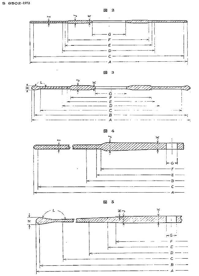
| Contour | Fig.2 | Fig.3 | Fig.4 | Fig.5 | Fig.5 | Fig.5 | ||
| A | Outer Diameter | 175+/-1 | 175+/-1 | 175+/-1 | 175+/-1 | 251+/-2 | 301+/-2 | |
| B | Diameter of raised Rim*3 | - | more than 173 | - | more than 173 | more than 247 | more than 298 | |
| C | Diameter: beginning of Music Groove*5 | less than 168 | less than 168 | less than 168 | less than 168 | less than 242 | less than 293 | |
| D | Diameter: ending of Music Groove*4 | more than 106 | more than 106 | more than 106 | more than 106 | more than 115.2 | more than 115.2 | |
| E | Finishing Groove Diameter | 97+/-1 | 97+/-1 | 97+/-1 | 97+/-1 | 106.4+/-0.8 | 106.4+/-0.8 | |
| F | Area of Label (diameter)*6 | less than 93 | less than 93 | less than 93 | less than 93 | less than 102 | less than 102 | |
| G | Hole diameter | 38.2+/-0.05 | 38.2+/-0.05 | 7.24+0.09/-0 | 7.24+0.09/-0 | 7.24+0.09/-0 | 7.24+0.09/-0 | |
| H | Max. thickness of outer rim | - | J minus 0.25 | - | J minus 0.25 | 1.5-2.3 | 1.5-2.3 | |
| I | Thickness of groove area | 0.6-1.2 | - | 0.6-1.2 | - | - | - | |
| J | Thickness of label area | 1.5-2.3 | 1.5-2.3 | 1.5-2.3 | 1.5-2.3 | 1.5-2.3 | 1.5-2.3 | |
| K | Skirt*1 thickness around hole | 0.6-1.0 | 0.6-1.0 | 1.35-2.3 | 1.35-2.3 | 1.35-2.3 | 1.35-2.3 | |
| L | Angle of raised rim*2 | - | more than 170degrees | - | more than 170degrees | more than 170degrees | more than 170degrees | |
| M | height from groove area to the highest label area | - | - | - | - | less than 0.38 | less than 0.38 | |
| REMARKS: | *1 | Skirt around hole shall cover more than diameter 43mm for 38mm hole and more than diameter 10mm for 7.2mm hole. The skirt thickness does not exceed Max. thickness of label area. Skirt area was designed originally for the purpose of playing at jukebox. | ||||||
| *2 | IEC etc recommended more than 175degrees while old JIS before 1969 proposed 165degrees because wider angle might make recorded grooves starting on the slope of rim. In 1969 JIS amended the angle to more than 170degrees thus approaching IEC. | |||||||
| *3 | IEC does not specified raised rim (groove guard) for 17cm records. This JIS followed RIAA concerning raised rim for 17cm records. | |||||||
| *4 | JIS S8502-1973 contained following explanation: "Outer diameters and various groove diameters are decided after researching the automatic players' actuating dimensions. Diameters for the end of music groove were not specified in IEC. One may think that this can be decided from finishing groove and lead-out groove. In 1966 JIS specified the diameters for the end of music groove in order to handle the record players equipped with auto-stop function." | |||||||
| *5 | RIAA in Bulletin E4 around year 1963 specified outmost music diameter 6 5/8"=168.275mm for 7inch (approx.17cm) records at both 45rpm & 33 1/3rpm. Beginning of music diameter for 30cm LP 293mm per this JIS is maximum compared with old IEC & RIAA:292.1mm from 11 1/2" and new IEC:292.6mm. | |||||||
| *6 | In standards (JIS/DIN/IEC/BS/RIAA), max. label area is specified while label size is not specified. Usual diameter of label (etiquette in French/Etikett in German) is around minus 2mm from max. label area diameter: label diameter 100mm average for 30cm LP and around 90mm for 17cm records. It seems that smaller size label paper is optional because some labels are found off-center. Label papers are usually pressed together with records (not pasted after pressing) - see Capitol USP 3635622. | |||||||
My analysis about the angles of raised rim. In case of 175degrees for raised rim, the maximum outer blank width from the edge to the recorded groove might happen to be more than 5mm. It contradicts with the maximum recorded outer diameter 292.6mm (though this is not contradiction since both maximum values are set separately-incompatible). There can be two ways of solution. The blank width can be reduced by setting rim angle as in case of old JIS. Another (more practical and simple) method is to make the recorded groove starting at inner radius (less than 144mm) or discontinue raised rim and make record flat with sufficient lead-in width. The latter is adopted in the recent design of records since groove guard became unnecessary for usual record players: stack of records for auto-changer is outdated.
The thickness of music groove area is not specified for the record with raised rim since the thickness of recorded area is usually increasing towards inner (the thinnest point is located at the foot of raised rim). Often the peripheral edge has burrs.
 In a cold winter day I screwed a record from shelf forcibly. Then it was broken.
So I had chance to measure thickness of this low-priced Seraphim (Toshiba-EMI)
record: Outer rim thickness 1.7mm/foot of raised rim 1.2mm starting music/middle
groove 1.3mm/inner groove 1.4mm/label area thickness 1.7mm.
In a cold winter day I screwed a record from shelf forcibly. Then it was broken.
So I had chance to measure thickness of this low-priced Seraphim (Toshiba-EMI)
record: Outer rim thickness 1.7mm/foot of raised rim 1.2mm starting music/middle
groove 1.3mm/inner groove 1.4mm/label area thickness 1.7mm.
I notice minor difference between JIS and BS/IEC drawings. The
thickness of music groove area looks unchanged (non-tapered) in BS/IEC drawings (or their
drawings do not clarify this specific point) while the thickness of the record
groove area is reduced towards the rim in many records. I think
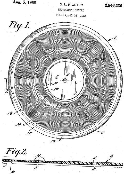
these records follow the contour as proposed in US
patent 2846230 assigned to RCA which tells as follows: label area
thickness, for example, be .075". The record groove area has a
maximum thickness immediately adjacent the label area. This maximum thickness is
slightly less than the thickness of the record at the label area. For example,
the thickness of the record groove area at its point of maximum thickness may be
.065". This record groove area tapers from the maximum thickness aforesaid
to a minimum thickness at the outer periphery of the record groove area. The
thickness of the record at the region of minimum thickness may, for example, be
about .045". Surrounding the record groove area, there is a marginal area.
The marginal area or portion has a maximum thickness greater than the average
thickness of the record groove area but less than the thickness of the label
area. The thickness of the marginal area may, for example, be of a thickness
corresponding to the accepted standard thickness for the rim of phonograph
records, whereby the record may be used with automatic record changers of
the type wherein the selection of the records is affected at the rim of
the record. This thickness may, for example, be .065" ...
I think
both master lacquer and stamper film are not tapered. Then groove of tapered design is little inclined? The rate of inclination at music groove is less than
0.2 degree from DEGREES(ASIN(0.35/100)) for example. Actual radius variance due
to small taper shape is negligible compared with the rate of expansion of nickel
stamper during heat press procedure. Stamper film or foil is flexible.
I find following drawing from US patent presenting the idea of raised
rim for sound groove protection. This patent referred to "the flexible
stamper" in making raised rim.
My note: This invention indicates lead-in
groove started in raised rim while usual record with raised rim is designed to
make lead-in groove starting from the end of raised rim. In my collection of
records I find both types. Raised rim near the edge of record has often
deformation so that I encounter problem of tracing on lead-in groove on raised
rim. Raised rim has advantage (reinforcing thin disc record and
protecting recorded area) and disadvantage (records tend to be warped due to torsion
during or after pressing process).
Drawing for 25cm and 30cm records. Middle values of outer diameter: 301.6mm/type III and 250.8mm/type IV each allowance +/-0.8mm.
Drawing for 25cm (type 2533) and 30cm (type 3033) records. Middle values of outer diameters: 301.6mm for Type 3033 and 250.8mm for Type 2533 each with allowance +/-0.8mm.
Thickness was specially defined in IEC 98 (1958)
E5 Disk thickness:The thickness of 78 rev/min coarse groove and 33 1/3
rev/min fine groove records shall be as follows:
The thickness of the thickest part of the record shall lie between the limits
of:
0.090 in (2.30 mm)
0.059 in (1.50 mm)
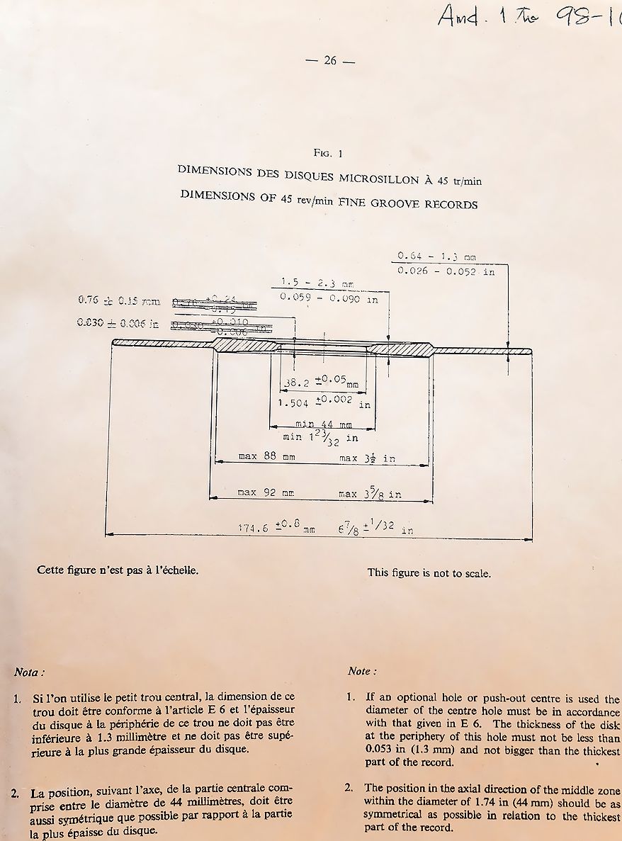
For the thickness of 45 rev/min fine groove records
see Fig.1, page.26.
IEC
98 (1958) had not indicated figures for LP and SP records.
Thickest part is located at label area so that rubber mat on platter has usually recess for label area.
| Item of Description | Standards | IEC98-1958 | RIAA-1963 | IEC98-1964*2 | BS1928-1965 | DIN45547-1981 | IEC98-1987 | JIS S8502-1973 |
| Recorded Outer Diameter (Max): beginning of groove | 292.1mm (11.5inch) | 11 1/2" | 292.6mm (11.52inch) | 292.6mm (11.52inch) | 292.6mm | 292.6mm | less than 293mm | |
| Recorded Inner Diameter (Min) | 120mm (4 3/4inch)*1 | 4 3/4" | Nil | Nil | 115mm | Nil | more than 115.2mm | |
| Finishing Groove Diameter (concentric) | Nil*5 | 4 3/16" +/- 1/32" | 106.4+/-0.8mm (4 3/16+/-1/32inch) | 106.4+/-0.8mm (4 3/16+/-1/32inch) | 106.4+/-0.8mm | 106.4+/-0.8mm | 106.4+/-0.8mm | |
| Lead-in Pitch | Nil | 1/32"-1/16" (0.8-1.6mm) | 0.8-1.6mm | 0.8-1.6mm with NOTE: maximum 1.2mm for LP having a raised rim | 0.8-1mm | 1.2+/-0.4mm | 0.8-1.6mm | |
| Lead-out Pitch | 6.35+/-3.18mm (1/4+/-1/8inch) | 2 to 6 grooves/inch(4.2-12.7mm) | 6.4+/-3.2mm (1/4+/-1/8inch) | 6.4+/-3.2mm (1/4+/-1/8inch) | 6.4+/-3.2mm | 6.4+/-3.2mm | 4-9mm | |
| Max. eccentricity of hole to groove spiral | 0.2mm(0.008inch) | runout of recording grooves relative to center hole: 0.050" max. (1.27mm) See Remark *7 about this figure | 0.2mm (0.008inch) | 0.13mm (0.005in) | 0.2mm | 0.2mm | Eccentricity 0.2mm max and warp (height change) 1.5mm max *3 | |
| Max. eccentricity of hole to disk periphery | 0.8mm (1/32inch) | 0.8mm (1/32inch) | 0.4mm (1/64inch) | Nil | Nil | |||
| Unbalance (allowable off-centre gravity) | Nil | Nil | Nil | 11.1mm(7/16inch)*4 | 8mm | 8mm | Nil | |
| Diameter of Centre Hole | 7.24 -0/+0.09mm (0.285-0.2885inch) | 0.286" +0.001" -0.002" | 7.24 -0/+0.09mm | 7.24 -0/+0.09mm (0.285-0.2885inch) | 7.24 -0/+0.09mm | 7.24 -0/+0.09mm | 7.24 -0/+0.09mm | |
| VTA (the reproducing stylus tip to cantilever fulcrum) | Nil | 15 degrees | about 15 degrees | 15 to 25 degrees*4 | 20+5/-0 degrees as VMA | 20+5/-0 degrees | VMA is not specified, but nominal 15degrees is suggested in appendix. | |
| Stylus Tip Radius (Spherical) | Monophonic: 0.020 to 0.026mm(0.8 to 1mil) | Stereophonic: desirable 0.5mil (0.013mm) | Stereophonic: 0.013 to 0.018mm(0.5 to 0.7mil) | with NOTE: "For both monophonic and stereophonic application, the preferred range of tip radius should be: 0.015 to 0.018mm (0.6 to 0.7mil)"*4 | Nil | Nil | Nil | |
| Monophonic: 0.013 to 0.025mm(0.5 to 1mil) | ||||||||
| Included angle of spherical tip | 40 to 50 degrees | Nil | 40 to 55 degrees | 40 to 55 degrees | Nil | less than 55 degrees | Nil | |
| Groove Angle | 88+/-5degrees | 90/+ 5 degrees | 90degrees | 90+/-5degrees | 90+/-0.7degrees | 90+/-5degrees | standard 90degrees | |
| Bottom Radius (Maximum) | 7.5micron (0.0003") | (6.35micron) 0.00025" | 4micron (0.00015") | 4micron/(8micron)*4 | 8micron | 8micron | 5micron | |
| Top Width of Groove (Monophonic) | >55micron(0.00215") | 0.0022"-0.0032" | >51micron (0.002") | >51micron (0.002") | *6 | Actual dimension: minimum 30micron (see my remark *6) | >50micron | |
| Top Width of Groove (Stereophonic) | Nil | Instantaneous 0.001" min | Nil | Nil (preferably not less than 25micron and average not less than 35micron)*4 | Average more than 35micron Instantaneous more than 25micron | Nil | ||
Remarks* on above table:
*1. In the first edition of IEC98 (Section F5 Page 21) the "minimum diameter of recorded surface" is quoted for transcription recordings (for broadcasting use) only. There is no corresponding description about minimum diameter for commercial disk records (Section E).
*2. I picked up the figures for IEC98-1964 from BS1928 as BS1928-1965 is based on 2nd edition of IEC(1964). Mirror documents with respective notes when BS differs from IEC descriptions.
*3. JIS prescribed for the quality of records as under and commented
on warps: "It is not easy to make rule
against warps which have complex forms and nature. Hence we checked
representative warps of wavy or shallow dish. On our investigation
such warps (height change) within 2mm will not cause any practical problem on playing
back such records, while it is not possible to control the way of storage and final
distribution to consumers. We observed that the warps less than 1.5mm at
production had not increased to warps more than 2mm under normal storage conditions at
distributors, so that we specified maximum warp to be 1.5mm."
How to
measure warps according to JIS: For dish-like warps, set height gauge on the
half radius of label area and push down both ends of label area flat with
fingers and measure the difference of height. For wavy warps, set height
gauge on the recorded outer groove (3-5mm from the rim of record) and rotate
the turntable slowly (=by hand?) more than one turn and measure the
difference of height. I have the impression that factory sealing
with shrink film itself as recent commercial practice is the cause of warp
after production (due to stress of film shrinkage) . Old records without
sealing were found much better than recent issues sealed with shrink films.
Or old records too had warps sometimes but such might be destroyed or
not resold so that old records on market are found to have less
warps. Or recent issues are produced under poor quality control or
check system since some pressed records have imperfection
(trimming error, off centre press, miss-press due to mould or uneven mixing
of materials etc) still in the process of analog disks production.
| DURABILITY AND SN TEST IN JIS S8502(DISK RECORDS) | 17cm EP | 25・30cm LP |
| S/N ratio(1kHz peak 50mm/s lateral recorded groove versus plain groove) with stylus force 4g+/-1g and tip radius 0.018mm+0.002/-0.003mm | more than 43dB | more than 45dB |
| Durability Test of groove and S/N ratio after 100times of plays on plain groove with stylus force 6g+/-1g and tip radius 0.018mm+0.002/-0.003mm | more than 40dB | more than 42dB |
| Eccentricity from the centre hole (maximum transition divided by 2) | less than 0.2mm | less than 0.2mm |
| Warps (24 hours after pressing and cooled down to normal temperature) | less than 1.5mm | less than 1.5mm |
| THE PICKUP SHOULD HAVE THE FOLLOWING FREQUENCY CHARACTERISTIC. I think it should be taken as minimum requirement for cartridge coupled with filters (LPF/HPF) in order to measure the output with the indication of VU meter. | ||
For comparison I introduce some common/accepted values of dynamic range and SN ratio among different analogue disks. Of course the same format/media can have different value according to circumstances. "Acetate/cellulose 78rpm" indicates instantaneous recordings for broadcasting use around 1950. I picked up these data from a dissertation (once downloadable, now missing).
| Media/Format | Dynamic Range | Frequency Range |
| Shellac 78rpm | 30-50dB | 150-6000Hz |
| Acetate/cellulose 78rpm | 50-60dB | 30-10000Hz |
| Vinyl 33rpm | 66dB | 30-15000Hz |
| Media/Format | Reference Signal (peak velocity) |
Frequency Band |
S/N (signal to noise ratio) |
| Shellac 78rpm SP | 7cm/s at 1kHz | 500-6000Hz | 17-37dB |
| Acetate/cellulose 78rpm SP | 7cm/s at 1kHz | 500-10000Hz | 37-47dB |
| NAB standard (1949) mono LP | 7cm/s at 1kHz | 500-10000Hz | 40dB |
| NAB standard (1963) mono LP | 7cm/s at 1kHz | 500-15000Hz | 55dB |
| NAB standard (1963) stereo LP | 5cm/s at 1kHz | 500-15000Hz | 50dB |
Exemption under 500Hz is related to usual recording characteristics. S/N for lower frequencies is not guaranteed due to crossover while S/N for higher frequencies is guaranteed due to emphasis (top-lift) on recording. See my excel file for equalizations (its first sheet "EXAM").
*4. As per Amendment Slip No. 1 published 26 January 1972 to BS1928-1965
*5. Diameter of concentric finishing groove 98.4mm was quoted for 45 rpm record. Corresponding finishing groove radius for 33.3rpm record was under consideration at the time. 106.4+/-0.8mm was quoted in DIN 45537(Monaural Records 33.3rpm) & DIN 45547(Stereo Records 33.3rpm) both Nov. 1962.
*6. DIN 45537 in 1962 (Monaural Records 33.3rpm) indicated top width: more than 55micron while bottom radius less than 4micron. By the way it is uncertain whether monophonic groove dimensions in stereo age/cutter were differing from monophonic groove dimensions in original monaural age/cutter or not. It may depend on the density of pitch (for example: original two sides recordings can be compressed to one side by the development of cutting engineering) or the cutting engineer's idea at the time. Since 1970 it was believed that the minimum top width of monophonic groove could be reduced to 30microns as indicated in IEC98-1987 though this standard has not clarified its application to monophonic groove. I think Amendment Slip No. 1 published 26 January 1972 to BS1928-1965 (where the tip radius 0.6-0.7mil can be commonly recommended for both monophonic and stereophonic application) is corresponding to this change of minimum top width for monophonic groove.
*7. RIAA in Bulletin E 4 (1963) commented "Note: This figure does not imply that a record having this degree of run-out would be acceptable from a quality standpoint. It does provide, for instance, a limit for the maximum sensitivity or a velocity trip when combined with the pitch of spirals between individual bands". My note: marker space between bands is 1mm pitch/turn usually. Four types of auto-lift-return mechanism for arms: a. Position Trip at specified radius of groove/ b. Progress Trip (finishing groove) / c. Eccentric Trip for SP lead-out groove/ d. Velocity Trip actuated by velocity of arm swing at lead-out pitch. Run-out 0.050" max. (1.27mm) in this RIAA standard is safeguard against actuating auto-lift-return mechanism for some auto players. For instance, velocity trip for Yamaha YP-D8 is adjusted around 3mm pitch/turn matching with the minimum lead-out pitch in standards. Anyway RIAA's explanation was not straightforward - it was better to specify max. eccentricity 0.01 inch or around. Maybe RIAA reserved such strict specification considering the status of record industries in those days.
In 1978 RIAA revised their
Bulletin E 4 DISC PHONOGRAPH
RECORDS FOR HOME USE incorporating metric as well as English unit of
measure, and using decimals rather than fractional dimensions. Their
standards for 78-rpm discs and serration standards for 45-rpm discs have
been deleted from bulletin. Also "the Standard Recording and Reproducing
Characteristic," Bulletin E 1 has been incorporated in 1978 version.
Remarking "These are dimensional standards to faciliate equipment desingn
and assure interchangeability. They are not intended to indicate or imply
quality or performance levels." Additional remark to *7:"The standard for
groove-runout or eccentricity has been revised from the old limit of 0.050"
to a Total Indicated Run-out (TIR) 0.016"(0.41mm)." It seems that this new
RIAA standards follow BS 1928(1965 and 1972 amendment slip) indicating Center of
Gravity as 11.1mm(0.437") etc.
Meanwhile
NAB[1964] showed
idealistic strict specifications: [clause 2.15] eccentricity of hole to
groove spiral within 0.005 inches (0.127mm) and [clause 2.20] warp height
"not be in excess of 1/16 inches" for one turn and "not exceed 1/32 inches"
for any 45 degrees segment. I think the latter demand [warp within 0.8mm
(1/32 inches) for any 45 degrees segment] is not always practicable since
some records have wavy warps at rims. If such is played with heavy pickup system,
stylus jumps. Hence light system (arm+pickup-head) is preferable. Low
inertia arm was developed mainly from 1970s.
B.S.1928-1965 was prepared and approved by the Acoustics Standards Committee consisting of BBC, British Electrical and Allied Manufacturers' Association, British Radio Equipment Manufacturers' Association, Radio and Electronic Component Manufacturers Federation etc.
JIS (Japanese Industrial Standard) S8502-1973 was prepared by RIAJ (Recording Industry's Association of Japan) and approved by MITI (=current METI).
Many German standards were prepared by the German Electro-technical Committee (Deutsche Elektrotechnische Kommission=DKE) in DIN (Deutsche Institut fuer Normung) and VDE (Verband Deutscher Elektrotechniker). "DKE" is combination committee between DIN and VDE since 13th October 1970. VDE has been leading group for making practical electric standards since its start on Jan. 1883. The history of DIN is little complicated: In 1917 NADI (Normenausschuss der deutschen Industrie=German Industrial Standards Committee) was founded, in 1926 DNA (Deutschen Normenausschuss=German Standards Committee) was founded and finally in 1975 current name DIN was adopted by changing its name from DNA. "DIN" does not stand for Deutsche Industrie Norm (German Industrial Standard) directly, but a standard approved by Deutsche Institut fuer Normung (German Institute for Standardization). But since any standard is implicitly connected with industry, DIN can be interpreted as Deutsche Industrie Norm (German Industrial Standard).
Beginning of groove (plain groove without signal)
Lead-in grooves (at least one turn): pitch 1.2mm+/-0.4mm per turn (we find some irregular records having wide lead-in pitch such as 2mm starting on the slope of raised rim). Usually 2-3 turns of 1.2mm pitch plus one reduced pitch before music groove. The stylus happens to fall in this groove. But actually stylus is landing more often between the grooves - then tip is dragged eventually into groove during one turn of record. The lead-in pitches of some records start in the slope of raised rim so that stylus tends to skip the grooves. Hence BS1928-1965 commented specially as follows: NOTE 1. For 33 1/3 rev/min records having a raised rim, it is desirable that the maximum lead-in pitch be 3/84 in (1.2mm) and the top width of lead-in groove be 0.004 in to 0.006 in (0.10mm to 0.15mm).
Beginning of music groove which has often additional turns of mute plain groove with normal recorded pitch (less than 0.15mm) before recording actual signal. Is it for stabilizing the arm or for timing of starting signal?
Marker space grooves for interval between bands: pitch per turn is around 1mm (1.6mm max). The marker space should not be located inner than radius 63.5mm (as per IEC98-1987) lest the auto-lift of player should be activated before the end of music groove.
Ending of music groove.
Lead-out grooves: when the lead-out pitch is exceeding 6.4mm/turn, the top width of groove shall be increased to more than 75micron according to IEC98(1964&1987). BS1928-1965 recommended minimum top width 0.004 in (0.10mm) irrespective of lead-out pitch width for fine groove records. My note: wider top width for wider pitch is safeguard against spiral tracing force especially at the junction from lead-out to finishing groove. Often narrow top width for wide pitch makes the stylus climbing over the groove wall and touching at the label! Usually the first & last lead-out pitch of spiral groove is narrowed more than normal lead-out pitch in order to avoid such accident.
Finishing groove: concentric loop for modern design of records. In the past eccentric loop was designed for 78rpm and early LP records activating automatic shut-off mechanism.
About the contours of fine groove and applied stylus, I find two drawings as under. The original sources of these drawings are unknown (left drawing was made earlier than 1955 because same was shown in Itoh's book-1955 while right one was shown in Yamamoto's book-1971). I suppose it might be originated from Monophonic Fine Groove record before stereophonici era since the applied stylus radius 1mil=25.4micron and top width 2.3mil=58.42micron are common in both drawings.
The bottom radius of groove is not specified in above left drawing while the maximum bottom radius 5micron quoted in above right drawing seems to correspond with JIS S8502-1973. We should be careful about the minimum and maximum figures in standards since the figures quoted there are specified as independent figures on different phase and not transferable actually in one simple figure or drawing - sometimes simplified drawing is the source/cause of misunderstanding. For instance, groove depth 23.6micron in the right drawing is applicable for top width 51.3 or 51.4 micron and bottom radius 5micron. The height gap between contact point and the edge of land 0.44mil (11.2micron) is applicable for top width 2.3mil (58.42micron) and stylus tip radius 1mil (25.4micron).
******************************************************************************************************************************************************************
A standard for SP records became definable only at the end of life ironically. In fact SP recordings were discontinued by 1964 in most countries including Japan.
IEC/BS have not shown any drawings of SP records except some limited descriptions: italic numbers or descriptions are shown only for comparison.
| IEC98(1964) & BS1955(1965): SPECIFICATION FOR PROCESSED DISK RECORDS AND REPRODUCING EQUIPMENT | RIAA Bulletin No. E 4 (around 1963): DIMENSIONAL STANDARDS DISC PHONOGRAPH RECORDS FOR HOME USE | |
| Thickness of record | For all types of record, the thickness of the thickest part shall lie between 0.09inch (2.3mm) and 0.059inch (1.5mm). This shall mean that vinylite instead of shellac is used on SP in this era. | 0.080" + 0.010" (2.032-2.286mm) for 10"record & 0.090" + 0.010" (2.286-2.54mm) for 12" record. |
| Minimum top width | 0.006inch (0.15mm). First edition IEC98(1958) specified same but commented: "To obtain an extended playing time 78 rev/min coarse groove commercial records with top width of 0.004inch (0.1mm) are also used in some countries. For such a groove the tip radius of the reproducing stylus should be 0.0023inch (0.058mm)+/-0.0002inch(0.005mm)." | not specified but maybe around 0.006inch as estimated from minimum groove depth for eccentric finishing groove: 0.003inch & its contour approximately same as music grooves |
| Maximum bottom radius | 0.001inch (0.025mm) | NIL |
| Included angle of groove | BS1955(1965):90+/-5degrees while IEC98(1964) does not give any tolerance for the included angle). First edition IEC98(1958): 88degrees+/-5degrees for commercial records and 85degrees+/-5degrees for transcription records | NIL |
| Centre hole diameter | Nominal 0.285"(7.24mm): 0.2850"-0.2885" (7.24-7.33mm) same as LP | Nominal (or mean value?): 0.286"(7.26mm) similar to LP |
| Shape of outer edge | NIL | (a) Semi-circular, or (b) "V" Where "V" edge is used, it is recommended that it have: (1) Included angle of 80 degrees + 10 degrees (2) Edge radius of 1/64" (approx.) (3) Apex of the "V" depart from the mid-plane between record faces by not more than 0.010" |
| Lead-in pitch | NIL | At least one complete turn between outer edge of record and recording pitch |
| Lead-out pitch | 1/4+/-1/8inch (6.4+/-3.2mm) | minimum 1/8inch (3.175mm) |
| Finishing groove: Eccentric type | 3 3/8 +/- 1/64inch (85.7 +/- 0.4mm). The eccentricity shall be 1/8 +/- 1/64inch (3.2 +/-0.4mm) with Note: "The eccentricity of an eccentric finishing groove is the distance of its centre from that of the groove spiral." | 3 3/8inch (85.7mm) with Run-out relative Center Hole 0.250" + 0.015" (6.35mm-6.73mm). This might be similar to IEC/BS in the left column. |
| Finishing groove: Concentric type | 3.386 +/- 0.039inch (86 +/- 1mm) | NIL |
| Diameter of outermost groove of recording pitch (Music Groove) | Maximum 9.52inch (241.8mm) for 10" record & 11.52inch (292.6mm) for 12" record. Same as RIAA | 9 1/2" + 0.02" (241.3-241.8mm) for 10"record & 11 1/2" + 0.02"(292.1-292.6mm) for 12"record. |
| Minimum Inside Diameter of Recording | NIL | 3 3/4" (95.25mm) |
| Recommended tip radius of reproducing stylus | Maximum 0.003inch (0.076mm) - Minimum 0.002inch (0.051mm) | NIL |
| Recording and reproducing characteristics | Time Constant: t1 50microsecond (toplift at recording & rolloff at reproduction 3183Hz)/t2 450microsecond (turnover 354Hz)/t3 3180microsecond (50Hz) with note: "In some countries, the fine groove characteristic is used on coarse groove records." | NIL (maybe RIAA LP characteristic was applied on SP too in latest SP recordings which used "vinylite" material instead of "shellac") |
About the contours of coarse groove and applied stylus, I find two different drawings as under. The original sources of these drawings are unknown (left drawing was made earlier than 1955 because same was shown in Itoh's book-1955 while right one was shown in Yamamoto's book-1971). I suppose these might be originated in different era or company: left one might be older or applicable on coarse groove transcription disk with minimum top width 100 micron and maximum bottom radius 38micron as specified in IEC98-1958 and right one might be latest commercial SP recording as described in IEC/BS/RIAA etc. Though top width and bottom radius differ, the applied standard stylus radius 2.5mil=63.5micron and groove depth 1.64mil=41.7micron are common in both drawings. However 2.5mil was converted to 65micron in IEC-98(1958) since conversion between inch and mm is optionally rounded i.e., the figures shall be taken as equivalent in the scale of each unit: The inch and metric dimensions are both recognized nominal dimensions.
When you look at these drawings, you will notice an essential difference - contact height of stylus on the groove. Providing that the stylus tip is formed spherical and that the included angle of groove is proposed as 90degrees for easier calculation, I calculate on trial as follows. (UNIT: micron)
| Top width | Maximum bottom radius rb | Imaginary Depth as 90degrees V groove=top width/2 | True Depth | Tip radius r | Distance of contact points as r*SQRT(2) | Contact Height from imaginary V bottom | Contact Height from true bottom | Clearance between contact height to land of groove | Clearance of tip bottom to groove bottom |
| 114.3(4.5mil) | 38.1 (1.5mil) | 57.15 | 41.4*(1) | 63.5 | 89.8 | 44.9 | 29.1 | 12.3 | 10.5 |
| 150 | 25 | 75 | 64.6*(2) | 63.5 | 89.8 | 44.9 | 34.5 | 30.1 | 15.9 |
A standard is a kind of the patchwork made from the past and current norms.
The following US patent shows an example of cutting stylus for SP. I add some descriptions in italic to original figures for prompt reference. Capps commented further: "during a recording operation the face 14 of the stylus is at an angle or 90 degrees to the surface of the blank being engraved or cut, although the 90degree angle may be varied approximately 5 degrees forward or backward."
Before standardisation of coarse groove lateral recordings per IEC98 and RIAA, various different groove dimensions including vertical (hill-and-dale) recordings for coarse groove had been adopted by various companies and times.
For example in US patent 2251204 by Reid tells the records of the laterally cut type as follows:
...it is common practice to cut the
sound track according to standard specifications as to width, wall angle and tip
radius. The standard width is 6 mils, or .006inch of an inch at the
surface of the record, and a V-shaped cut is made, the walls of which are at
an 88 degree angle with each other. This is termed the wall angle. The bottom of the
groove is designed to be cut on a radius of 2.3 mils, and this rounded surface
is tangent to the walls.
These specifications govern the
groove depth which should be 2.1 mils at a vertical center line bisecting the 88
degree wall angle. Slight variations in the type and shape of the cutter, the
weight imposed thereon and other factors and conditions of recording often cause
departures from the foregoing standards but the same fairly represent the
average desired or maintained by most manufacturers. ...With the exception of
steel needles, all reproducing styli had a small rounded point having a radius
of about 2.3 mils. Top quality styli were kept within plus or minus .1mil or
about 4% of 2.3 mils. Styli having radii more than 2.4 mils were classified as
seconds, and if the radii exceeded 2.7 or 2.8 mils, or about 20% of
2.3 mils they were discarded as virtually useless since they caused an increase
in wear and because they had other serious disadvantages.
"The bottom of the groove is designed to be cut on a radius of 2.3 mils"? Then standard spherical stylus 2.3mils shall land in the groove having full line contact or bottom contact as shown in Fig.1. IMO: this shows the change of "standard groove modulation" from vertical=hill-and-dale recording (stylus to have bottom contact) to lateral recording (stylus to have side contact). For the purpose of side contact and faithful tracing on lateral modulations, Reid proposed bi-radial reproducing stylus (r0.5 x R4 mils for example) though his idea of top contact (areas of A and A' in Fig. 1) was not practical. The irregularity of groove is often found at the bottom and the top edge of land. Hence the regular spherical tip is designed to contact around the middle height of walls and free from the bottom of groove. And the standard bottom radius of SP is changed from average 2-2.3 mils (around 1940) to maximum 1.5 mils for transcription recordings and maximum 1 mil for commercial recordings as per IEC98 (1958).
US patent 2464032 (applied in 1945 and patented in 1949) by Franz and assigned to Dictaphone Corporation tells:
Sound recordings may be made upon comparatively soft
plastics such as wax, or upon harder materials such as aluminum, or upon a
number of thermo-plastic compounds - particularly ethyl cellulose, cellulose
acetate, cellulose nitrate and several of the vinyl compounds.
When
recording on these materials, two different systems have been used. One, used
particularly with the softer plastics, consists in the actual cutting of a
groove out of the material. This requires a cutting stylus made from very hard
steel or preferably sapphire or diamond. The tip of such a stylus is usually
made in V-shape with a flat front practically perpendicular to the material
which is being engraved. The point of the V is not sharp but is rounded off at a
small radius of from 0.001 inch to 0.003 inch. The standard for disc recording
is 0.0022 inch. The cutting of these harder materials requires a sharp stylus.
In order to maintain the requisite sharpness, it is necessary to regrind or
replace the stylus at frequent intervals.
The other system
of recording is the embossing method. It does not require frequent stylus
replacement and does not involve throwing off a chip which would have to be
eliminated in some manner. When embossing, the recording stylus causes the
material to flow to each side of the stylus. The record material has to be soft
enough for this flowing to occur smoothly and uniformly and the stylus has to be
so shaped that the flowing occurs in such a manner that the smoothest possible
groove is produced: and it must give a recording of satisfactory frequency
response.
The embossing recording method was widely adopted in dictating machines or instant recorders, but not used in high fidelity recording, so Franz referred deliberately to the satisfactory frequency response of emboss recording on soft plastics. Here the term "emboss" is meaning "not engraving but impressing" probably because the land looks like being embossed as in above document:"the material to flow to each side of the stylus". Edison's cyliner belongs to this type: Edison called "indentation" in USP200521. David L. Morton Jr. in his book(2004) SOUND RECORDING explains: "The cylinder had a shallow, spiral groove machined into its surface, which provided some space into which the tinfoil was pushed as it was embossed."
US patent 2573723 tells about the variations of grooves found in transcription recordings and commercial recordings:
Transcriptions commonly in use have a
groove shape whose radius of curvature varies from .0015 to 0.002 inch. Many 78
R.P.M. [commercial] records have groove radius as large as .003 inch. This
difference in groove radius is further complicated by the differences in the
angle between the groove walls, which commonly varies from 70 to 87 degree.
Early designs of styli calculated to avoid contact with the groove bottom were
founded upon the groove width ...In view of the groove width variation resulting
from the line per inch variation of 96 to 150 incident to modern recording, no
single groove width is an acceptable criterion for an universal stylus.
It is therefore an object of this invention to provide an universal stylus for
reproducers which fits with two points of contact and a small circle in any
record groove from the smallest transcription groove to the largest 78 R.P.M.
type record.
Note that the included angle of stylus is indicated 45degree and a radius of 3.5 mil toward groove bottom: effective frontal radii of contacts each 0.6 mil toward 45 degree. But then how about effective side/lateral contact radii? The contact area is not circular in this modern stylus. Commercial spherical stylus available in market is indicating only nominal radius. So-called "spherical" stylus tip ground from cone is not sphere actually and far from uniformity. As regards the variation of groove contours, please look into US patent papers by J.D. Reid: 2584922(1952)&2686679(1954) about Universal Reproducing Stylus, from which I edit one page for prompt reference.
There were such trade catches as "silent" or "mute" needles for SP around early 1940s because there was a demand for low needle talk directly radiated from friction, suppressing high frequency resonance or scratch noise mechanically without using electric filter. Typical invention may be as under: Roy Dally working then in Webster Electric invented cartridges for Electrovox and GE later. Another make of stylus for SP was curved one since straight stylus member was thought to cause high needle talk. Another make of stylus for SP had fancy flare or knot or spring etc on stylus arm to obtain selective compliance between lateral and vertical directions and evade disturbance such as pinch effect? Pinch effect was big problem in SP era not because of distortion as in stereophonic era, but because of both stylus and record wear due to higher vertical mechanical impedance of pickups in that era - See USP2379782-1945 assigned to Philco. Most stylus tips and shanks for SP era were inclined backward (not straight up) generally in order to reduce kinetic friction between stylus and groove - See USP2577149-1947 assigned to Unioncarbide suggesting 15degrees (measured from vertical axis) inclination of synthetic sapphire tip. Resilient material such as cushion rubber had been also used widely for stylus holder [USP1397835-1921/2625401-1953 etc]. Percy Wilson's compilation "GRAMOPHONES Acoustic and Radio" (page 21) in 1932 referred to this issue as "Needle Angle" and commented as follows: "Some says that an angle of 50 degrees (measured from horizontal axis) reduces surface noise and minimize needle hiss. This may be so, but experiment shows that this is always at the expense of some detail in the music. The best compromise is an angle of about 60 degrees, though a little divergence either side (57.5 or 62.5) makes little or no difference."
"The Columbia Long-Playing Microgroove Recording System" was reported in Proceedings of the IRE(=current IEEE) Aug. 1949 Volume: 37, Issue: 8 On pages 923- 927 by Goldmark, Snepvangers and Bachman. The following is abstract.
The Columbia LP (long-playing) microgroove recording system was developed to fill the need for music reproduction which would avoid interruptions not intended by the composer, and which would be of excellent quality at a reasonable cost. This allimportant factor of cost and the public's familiarity with the handling of phonograph records made it desirable to solve the task on the basis of records, rather than tape or wire. Standard 78-rpm records were originally designed to generate sound mechanically by direct transfer of energy from the groove of the record to the vibrating diaphragm. Because the entire acoustical energy had to be extracted from the grooves, these had to be quite rugged, and remained so up until now. The new Columbia recording system was an inevitable outcome of the use of electrical amplification between the groove and the loudspeaker. Today, practically no mechanical energy needs to be extracted from the groove, and thus, for the first time, it has been possible to develop much finer grooves, permitting longer playing time and distortion-free reproduction.
Old patent papers often tell us about the situations and problems at the time [transit from SP to LP] more vividly than any secondary source: for example one US Patent 2,681,388 (application date March 3, 1949/patented in 1954) invented by Goldmark and Snepvangers about Phonograph Pickup [Stylus Turnover type Crystal Pickup] tells as follows:
The standard phonograph record disk which
have been available to the public for many years is a sound record disk rotating
at 78 R.P.M. and having a sound groove spiral of the order of 100 convolutions
per inch. The groove is laterally modulated in accordance with the sound
to be reproduced and the maximum amplitude of excursion is approximately 0.002
inch. The tip radius of the stylus employed for reproducing these records
is usually about 0.003 inch. The pickup arm weights commonly give a vertical
force at the stylus of 30 grams or more, although in a few instances somewhat
lighter arms have been used. The records are usually available in 10-and 12-inch
sizes, the latter yielding a maximum playing time of approximately 4
minutes and 20 seconds on one side.
There have recently been made available fine-groove
long-playing record disks having more than 200 grooves per inch and rotating at
33 1/3 R.P.M. With a 12-inch diameter, such records yield maximum playing times
in excess of 20 minutes per side. the maximum amplitude of excursion of
the lateral modulation is of the order of 0.0009 inch. Due to the fine groove,
the tip radius of the stylus is much smaller than for the previous standard
record, and is approximately 0.001 inch. Very light stylus weights are employed,
of the order of 6 grams.
Inasmuch as many millions of 78 R.P.M. standard
records are now in the hands of the public, it is highly desirable to provide a
reproducer arm which is capable of reproducing either the standard coarse-groove
records or the newer fine-groove records alternatively. The difference in
fineness of grooves requires styli of different tip radii. Separate cartridge
could be employed, each designed for the reproduction of one type of record
only. These could be used with separate arms yielding different stylus weights.
Such duplication adds expense and increases the space required for
mounting.
The present invention is directed to the provision
of a pickup cartridge adapted for use in a single pickup arm and having two
styli whose tip radii are appropriate to the two types of records. In order to
avoid the necessity for changing the weight of pickup arm when employing
different styli, the cartridge is so designed that both standard, coarse-groove
and long-playing, fine-groove records may be played with a very light stylus
pressure. With such light pressures, the needle point compliance must be
carefully correlated with the other characteristics of the arm so as to provide
proper tracking during reproduction, and avoid any danger of jumping
grooves. It is also desirable that the output of the pickup cartridge be
approximately the same when playing either type record so that overall
amplification need not be changed when going from one record to another.
In accordance with one feature of the present invention,
different compliances are employed in the suspensions of the two styli , the
compliance for the coarse-groove record being greater than for the fine-groove.
The higher compliance permits the stylus to follow the greater amplitude of
excursion of the coarse-groove records while maintaining proper tracking,
and also tends to equalize the responses for the two types of records. It is
highly desirable to employ cantilever suspensions for the styli so as to permit
proper vertical and lateral compliance to be obtained. Preferably two
approximately horizontal cantilever arms are employed which tend in opposite
directions from a stylus mounting attached to a transducer for converting
mechanical movement into an electrical signal. Advantageously, a piezoelectric
crystal is employed which is secured at the top and has the double stylus
mounting attached tot he bottom so as to convert lateral movement of the styli
into electrical signals.
In order to further equalize the outputs of the two styli
when engaging respective records, a resilient damping element may be affixed to
the pickup cartridge in position to be engaged by the top of the larger stylus
when in playing position. This also serves to smooth the response for the
coarse-groove records.
With the double cantilever arm suspension which is
preferred, it is found that peaks in the response characteristic occur at
certain frequencies due to the presence of the arm not in use. In order to
remove these spurious response peaks, a resilient damping pad is affixed to the
arm in position to be engaged by the stylus not in use. This damping pad
prevents vibration of the unused stylus and hence prevents it from affecting the
response characteristic of the stylus in use.
In using the reproducing arm of the invention, the pickup
cartridge is rotated as a unit to bring the proper stylus into playing position.
This movement results in the engagement of the unused stylus with the damping
pad affixed to the arm. When it is desired to play a record of the other type,
the cartridge is simply rotated to bring the other stylus into playing position.
Suitable provision should of course be made to change the turntable speed for
the two types of records.
Similar dual stylus pickup with Variable Reluctance generating system was realised by GE as under.
During the period of transition from SP to LP, also dual playing stylus (common one tip used for SP/LP) was invented because turnover type was troublesome: DE885163 Universal Doppelnadeln, GB689873 (invented by Hermann Thorens) and GB692331=USP2759732 (Philco Corp) - these patents were published in the same year 1953.
US Patent 1,246,651(1917) illustrates the early situations of talking machines [before electric recording and reproduction] as follows.
Numerous patents have been granted on
records having grooves of various configurations. The earliest form was that
traced on a smooth surface covered with carbon dust. This carbon was displaced
and left a shallow groove in the carbon. The next step was the production of a
groove by indenting in a metal foil or in wax or by the concurrently devised
method of tracing through a wax film deposited upon metal and then etching; then
followed a cutting tool which formed a groove with sloping walls and a flat
bottom similar to a standard screw thread. Then followed a shallow round
bottomed groove cut in relatively hard material. This was followed by grooves of
semi-elliptical shape and of considerable depth. Then came the V shaped groove.
These forms are mentioned as commercially developed but in fact the early
experimenters tested many thereof concurrently, being limited only by their
several choices of materials. Various other forms of record grooves have been
suggested but all of them are along the same general lines as noted above.
In all of the record grooves with which I am familiar
the walls of the groove terminate at the plane of the record surface in sharp
angles and form sharp and consequently thin fragile edges. The sharp thin edges
are, because of the nature of the material of which records are composed, more
or less ragged or what is know in a cutting tools as "wire edged," and
rough edges produce false vibrations even upon the first use of the record. The
fact that the edges of the grooves are rugged causes them to crumble and
disintegrate by reason of the friction of the reproducing stylus against them
and in a comparatively short time the edges are broken down and the effect of
false vibrations induced by them is greatly increased. The rough edges of the groove also act as grinding surfaces against which the
stylus is held and consequently it is soon worm to such an extent that shoulders
are formed, which shoulders rest upon the surface of the disk and further tend
to produce discordant sounds. This grinding action on the stylus or needle is so
rapid that in most cases, before the needle reaches the end of the record groove
on its first reproduction the same is clearly noticeable and the nearer to the
end of the groove the needle approaches the greater the wear on the needle and
the record and the more apparent becomes the distortion of the sound
reproduction.
The reproducing stylus before electric recording era was designed to fit in the groove having bottom contact while modern spherical stylus for lateral and stereophonic modulations is tracing on the middle height of groove so as to have enough clearance from both the bottom of the V groove and the edges of land at top. Bottom contact on a groove with large bottom radius (arc shape) was required in accordance with heavier stylus forces. Though the electric recording system had been established by the end of 1920s, yet electric reproduction of records became popular only after radio equipment having amplifier for speaker was popularised. In case of mechanical/acoustic reproduction, rather big stylus force was necessary since mechanical pressure/displacement was transduced into acoustic power (loudness): think how to drive the diaphragm of sound-box mechanically.
| Mechanical Reproducer such as Sound Box | Electric Transcription Reproducer in 1940's | Reproducer for Shellac & Vinyl Records in 1950's | High Fidelity Reproducer for Vinyl Records | |
| Approximate vertical tracking force (average) | 80 - 250g (150g*) | 1 - 2 oz/28-56g | less than 12g (6g) | less than 3g |
| Material of stylus tip | steel, brass, tungsten, boron, jewels, thorn, fibre, bamboo, briar wood etc | Sapphire/Diamond | Sapphire/Diamond | Diamond |
| The above tracking forces are
average. There have been untimely reproducers which need
special tracking forces. Usually VTF (vertical tracking force) is not
clearly stipulated in standards since such is submitted to the
manufacturers of respective pick-up system. Standard is only a recommendation and
does not enforce obedience upon the makers. * average 150g for sound-box: by chance I find the following passage in Modern Gramophones and Electric Reproducers by P. Wilson and G.W. Webb (1929) P.144 "Clearly the pressure between needle and record affects the amount of wear, since the frictional force is proprtional to it. For other reasons, however, it is not advisable to reduce this pressure below about 4 oz, and in the authors' experience a pressure of 5 to 5½ oz is preferable. But on no account should the pressure be increased beyond 7 oz." I interpret above "For other reasons": small stylus pressure cannot drive the diaphragm efficiently or the stylus is mistracking due to the stiffness of diaphragm. |
||||