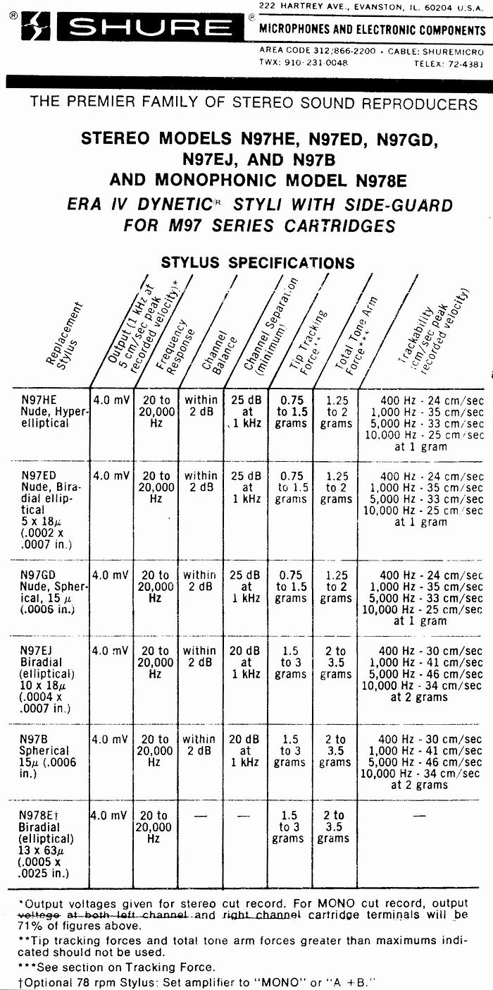
MJ/DENON(誠文堂新光社)とHFN(英国HiFi News)のテストレコードを入手しました。テストできる項目は以下のとおりです。HFNのレコードには各種Protractorsを組み合わせた紙の円盤シートが付いていてカートリッジ位置の調整の要旨が把握できます(Linear OffsetやNull Pointsの意味するところが一目瞭然)。
| HFN/Producer's Cut by Len Gregory, `The Cartridge Man` (2002) | |||
| MJ/DENON (1999) distributed by SEIBUNDO-Shinkohsha (Japan) | |||
| HFN | MJ/DENON | ||
| TEST ITEMS | Band | Band | |
| 1 | Channel Identification | A1 (voice) | A1-4(L/R/L+R/L-R 1kHz) |
| 2 | Phasing Test | A2 (voice) | A28-31: 0.2Hz and 0.1Hz difference between R/L for observing xy Lissajous wave with oscilloscope (L+R) |
| 3 | Channel Balance | A3 (pink noise L+R) system balance | A1-4: L/R/L+R/L-R 1kHz |
| 4 | Pink noise | A4 (L) & A5 (R) -20dB pickup output balance | |
| 5 | Bias setting (anti-skate) | A6-9(300Hz) +12/14/16/18dB | A-21: Flat Zone without grooves |
| 6 | Tracking ability | B1 & B4 & B8 (300Hz) +15dB | A15-16: 300Hz 50µm & 70µm (peak velocity 9.4&13.2 cm/s lateral) |
| 7 | Lateral resonance | B2 (25-5Hz) | B1: Sweep3-100Hz 45micron at L channel B2: Spot3-15Hz 45micron at L channel with cue 1kHz at R channel. |
| 8 | Vertical resonance | B3 (20-6Hz) | |
| 9 | Cartridge alignment | B5 (L-R 300Hz) | |
| 10 | Residual system noise/Rumble noise | B6 (unmodulated groove) | |
| 11 | Full range frequency (RIAA) | B7 sweep 20Hz-20kHz: This band is recorded at low level & groove radius around 8.5cm | A5-14: Spot L+R -13dB (lateral peak velocity 1.12cm/s is equivalent to peak velocity 0.8cm/s for the output of stereophonic cartridges). |
| 12 | Reference Level (0dB) at 1kHz | Reference level is not specified? | A1-4 (L/R/L+R/L-R): peak velocity 3.54cm/s 45degrees for L or R and peak velocity 5cm/s for lateral (L+R) or vertical (L-R) so that one channel output of reliable stereophonic cartridge should remain same among these modulations. |
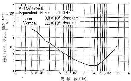
| 13 | Mechanical impedance at 100Hz | A17 amplitude 50µm (lateral peak velocity 3.14cm/s) | |
| 14 | Wow-Flutter test | A18 3.15kHz (L+R) | |
| 15 | IM distortion | A19-20 5kHz+5.4kHz and 8kHz+8.4kHz(L+R) | |
| 16 | Crosstalk test | A4 (L) & A5 (R) | A22-27: 300/1k/5kHz(L) and 300/1k/5kHz(R) |
| 17 | Tuning tones | A32-35: 440/442/444/415.3Hz | |
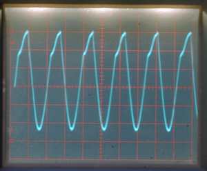
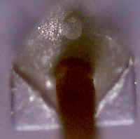
上記項目6のTrackabilityをテストしてみました。針圧が推奨値下限より少ないときの画像です。アンチ・スケーティングの調整よりも針圧増加の方が効き目があり、アンチ・スケーティング0でも針圧を2割増(推奨値上限)にすると綺麗な正弦波になります。又、音溝振幅が少なければ針飛び(片面の溝壁から接触が離れる意味で飛び出すわけではない)も起こらないようです。アンチ・スケーティングの調整が不十分でもクリティカルな溝では同様の波形が現れます。
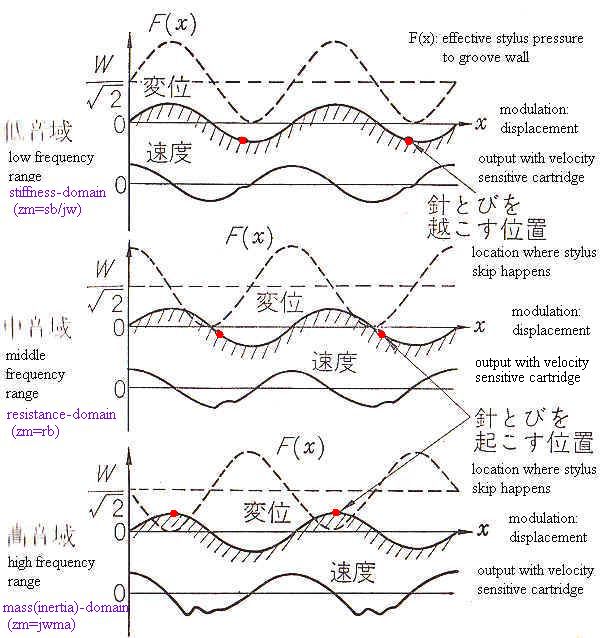
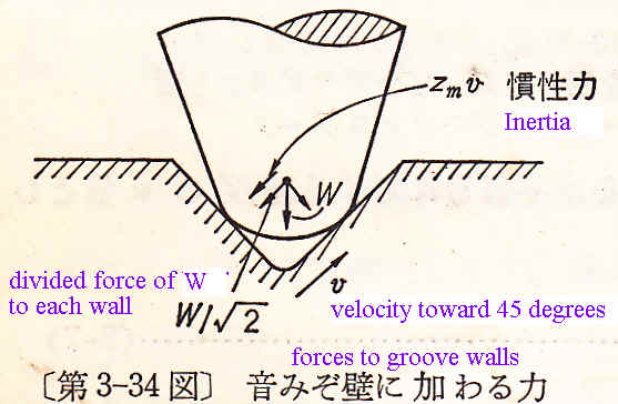
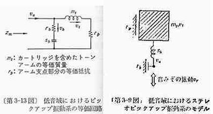
針とびが起こるメカニズムについては山本氏「レコードプレーヤ」P.108-110に「音溝壁に加わる力と針飛び現象」として以下の説明図があります。上記のオシロスコープ波形は300Hzのものですがstiffness controlled domainの低音域で針飛びが起きていると推定される。この図ではstiffness とresistance制御域との中間1kHzを中音域とし、質量制御域10kHzを高音域としているらしい。瞬間的針圧F(x)が0もしくはマイナスになる箇所で針とびが起こるが、その箇所は音溝の周波数によって異なる。実際のカートリッジではstiffness/resistance/mass controlled domainにそれぞれ違いがありそれらがtrackabilityを決定しているようです。例えば振動系等価質量が軽いものは高域再生能力も比較的高い(その領域のmechanical impedanceが低い)。ダンパーのstiffness(=1/compliance)の小さなものほど軽針圧で低音域が再生できる等々。
The following drawing No. 3-52 (Yamamoto) indicates some relations among variation of effective stylus pressure F(x) for 45 degrees, groove modulation (displacement) for 45 degrees and one channel output of stereo cartridge showing where the mistrackings occur.
Though it is too much complicated for me to explain in details,
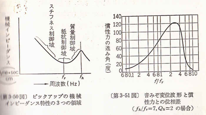
the background of the above is based on following explanatory drawings. No. 3-50
indicates three different (stiffness/resistance/mass or inertia controlled)
domains of mechanical impedance curve (so to say bathtub), 3-51 indicates one
sample of the phase difference in degrees between displacement and inertia
force (fh/fr=7, Qh=2 as representative values because most cartridges have
damping rate Qh around 2 for high frequency. :
Qh=SQRT(Ma(sb+sr)/rb)).
Ma(effective mass of stylus vibrating system), sb(stiffness around armature)
sr(record stiffness) rb(resistance around armature)
F(x) = W/SQRT(2)+[zm]
v = W/SQRT(2)+[zm] jw v/jw
Since v/jw represents the displacement of
groove modulation, the phase difference between inertia and sound groove shall be
decided by the phase of [zm]jw.
In stiffness domain: inertia force is in-phase
with displacement and delaying 90degrees in comparison with velocity.
In
resistance domain: inertia force is in-phase with velocity and advancing
90degrees in comparison with displacement.
In inertia-domain: inertia force
has reverse phase with displacement.
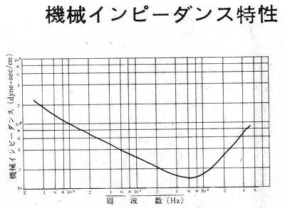
Details about mechanical impedance
[zm] are explained in the technical sheet of DENON
test record XG-7001
上記項目5のBias settingをHFNのレコードでテストしてみました。300Hz(L+R)の +12dB/14dB/16dB/18dBの4つのバンドに分かれています。45度方向peak出力感度1mV/cm/sのADC XLM improved MKIIでトレースしたとき+12dBのバンドで約7mV(0 to peak)、+18dBのバンドで約14mV(0 to peakになりました(テスターではなくオシロスコープのキャリブレーション・シグナルで波高スケールを校正して観測)。これからするとHFNレコードの0dB(300Hz)は水平方向でpeak 2.5cm/s、45度方向でpeak 1.77cm/sとしているらしい(recording level at 1kHzは示されていませんがイコライザーを通した後=直読ではなく300/1000Hzのphonostageの出力比で換算するとx1.88なので水平方向で1kHz 4.7cm/sになりpeak 5cm/sに近くなります)。最後の音溝は内周側の録音限界速度振幅(<線速度)20cm/sに近くなっています。実際にトレースしてみると最後のバンドでは針圧上限1.5gでアンチ・スケーティングバイアスを最大にしても歪みました。MA-505とこのADCカートリッジを組み合わせた場合針圧1.3g・バイアス楕円針位置に調整すると+16dB(水平振幅約83µm)の音溝まで問題なくトレースできました。MJの方は同じく300Hz(L+R)水平振幅50µm(速度振幅9.4÷√2=6.7cm/s)と70µm(速度振幅13.2÷√2=9.3cm/s)で針圧とトレースをチェックするようになっています。ステレオカートリッジに対して水平peak速度振幅÷√2=peak速度振幅としたのは簡単にいうと水平振幅を45度方向振幅に換算したためです。ステレオピックアップでモノラル(水平記録)を再生した場合、同じ速度振幅のステレオ溝(片壁録音)と比べると出力は1/√2=71%になるーあぁ、ややこしい㊟ステレオカートリッジの出力について参照。Shure M97の純正交換針の栞にも"Output voltages given for stereo cut record. For MONO cut record, output voltage at both left channel and right channel cartridge terminal will be 71% of figures above." とありました。
項目9のHFNのCartridge alignment(Azimuth)調整バンドについてはその用途が疑問です。というのも出力感度=チャンネルバランスなどが左右揃ったカートリッジでないとL/Rの出力差によりそのモノ=並列逆接続出力が最低の時最適なアジマスとはならないからです。例えば、合成出力が少なくなるようにカートリッジを傾けて調整すると傾いていたほうが出力が少なくなる(片側のクロストークも少なくなる)ことがありますが左右トータルでのチャンネルセパレーションは悪化しました。セパレーションはカートリッジの造作の問題でユーザーの問題ではないと感じます。いろいろ弄ってみたい人が多いのがオーディオという趣味でしょうか?
モノラルカートリッジの出力測定は水平記録(Lateral Recording)=モノラルレコードで測りますので簡単ですがステレオカートリッジは45度方向のL又はR片壁記録かL+Rの水平記録で測ります。ややこしいのはステレオL+Rは信号が同相であれば水平記録モノラルになることです(45/45方式のステレオと水平記録モノラルとの互換性)。
MJのテストレコードA1-A4のバンドには1kHzの基準信号(L片壁/R片壁/L+R水平/L-R垂直)が入っています。速度振幅はそれぞれ3.54/3.54/5/5cm/sですがステレオカートリッジでトレースするとどれも同じ出力になります。何故でしょう? ステレオカートリッジの発電機構のポールピース(MM)は45度方向に互い違いに配置されています。L片壁/R片壁の45度録音では片側100%出力で他チャンネル0%出力(右の図では緑マルの回転軸が45度になり回転中心軸側のチャンネルは発電しない)。一方、水平録音と垂直録音ではチャンネル当たりの出力は1/√2=71%。下の右図の中心の緑マルに注目するとそれぞれ<上下を軸とした回転>と<左右を軸とした回転>になります。実際には支点が完全には固定されていないので他チャンネルに漏れ(変位は少ないが速度振幅が早い)高域でセパレーションは悪くなるようです。
さて、アームの実効質量とカートリッジのコンプライアンスが実際どうなっているか検証してみます。標準になるカートリッジ・アームがあればお相手の値がそれぞれ確定できるのですが、信用できる標準を作っておかないと、共振周波数だけ分かっても別の組み合わせに応用出来ません。
アームMA-505の実効質量はhttp://www.fl-electronic.de/analog/tonarme.html(出典はHiFi Choice)によると14.5g。当時の標準シェルは単売シェルH-303(9.7g)と似ているが14.5gというのがシェル込みかシェルなしかも分からない。
測定条件:周辺温度は17-18℃(本当は20‐25度が望ましい)、湿度40-50%
データ集計:100Hzで針飛びを起こさない最低針圧Wc(g)とコンプライアンスの関係は水平信号振幅(a=50µm)のMJのテストレコードでは機械インピーダンス[Zm]=980・Wc/vh, 速度振幅vh=2pfa, コンプライアンスc=1/2pf・[Zm]からc=a/980Wc=50x10(-4)/980Wc(cm/dyne)になる。山本氏の式では音壁にかかる針圧 W/SQRT(2)<[Zm]x[v45]の時針飛びが起こるとしているが、速度振幅v45は45度方向のピーク速度なので水平速度振幅v/SQRT(2)と同等とすれば結局MJの式に集約される・・・と思っていたがそう簡単ではない。機械インピーダンスもコンプライアンスも実際には水平・垂直・45度で異なっているから。
Mechanical impedance Zm=980xWc/Vh (dyne・sec/cm) ---(Eq 1)
where Wc=minimum tracking force starting mistracking, Vh=velocity of horizontal
amplitude(cm/sec), horizontal amplitude=Ah(cm), Vh=2pifAh(cm/sec),gravity
acceleration=980cm/sec2
Compliance (as 1/stiffness)=1/(2pifZM) (cm/dyne) --- (Eq 2)
Eq 2 can be modified after substituting Eq 1 as follows:
C=Vh/2pf・980・Wc=2pf・Ah/2pf・980・Wc=Ah/980Wc --- (Eq 3)
Thus if Wc(g) & Ah(cm) are given, then dynamic compliance at specific frequency is ascertained.
For example, when f(requency) is 100Hz, Amplitude(horizontal displacement)
50micron=50x10^-4(cm) and Wc is measured as 1g, then
C=50x10^-4/980=5.1(10^-6)cm/dyne. But this compliance is at specific
frequency. How about resonance frequency?
| Arm:MICRO MA-505(Effective Mass:14.5g excluding shell?) | Dynavector DV-50A | Denon DL-110 | Sony XL55Mono | Ortofon SPU-G Classic | ADC XLM improved MKII |
| Nominal Compliance (10⁻⁶cm/dyne) | Static 20 | Dynamic 8 at 100Hz | Static 17 | Dynamic 8 at 10Hz | NIL |
| Head Weight (cartridge+shell) HW | 20.9g(=4.4+16.5) | 18.2g(=4.8+13.4) | 24.5g monocoque | 32g monocoque | 14g (5.5+8.5) |
| Total Arm Effective Mass including HW | 35.4g | 32.7g | 39g | 46.5g | 28.5g |
| Lightest VTF threshold for mistracking at 100Hz lateral displacement 50µm: Wc(g) | 0.4g | 0.75g | 0.6g | 1.7g | 0.4g |
| Compliance (10⁻⁶cm/dyne) at 100Hz calculated from Wc | 13 | 7 | 9 | 3 | 13 |
| Horizontal Resonance calculated from above data | 7.4Hz | 10.5Hz | 8.5Hz | 13.5Hz | 8.3Hz |
| Horizontal Resonance? - measured | about 6Hz | about 7Hz | about 7Hz | about 10Hz | 8-9Hz |
| Compliance (10⁻⁶cm/dyne) at horizontal resonance frequency | 20 | 16 | 13 | 6 | about 12 |
| Vertical Resonance - measured | unclear | 8-10Hz | Unnoticed due to Mono pick-up | 12Hz | around 12Hz |
| Compliance (10⁻⁶cm/dyne) at vertical resonance frequency | ? | more than 8 | ? | less than 3 | about 6 |
| Arm: Infinity Black Widow (Effective Mass:6g? 3g as per catalog in 1977) | Dynavector DV-50A | ADC XLM improved MKII |
| Nominal Compliance | Static 20 | Static 50? |
| Cartridge Weight including screws/nuts (HW) | 5g (4.4+0.6) | 6g (5.5+0.5) |
| Total Arm Effective Mass including HW | 11g | 12g |
| Lightest VTF threshold for mistracking : Wc(g) | 0.4g | 0.4g |
| Compliance at 100Hz calculated from Wc | 13 | 13 |
| Horizontal Resonance calculated from above data | 13.3Hz | 12.7Hz |
| Horizontal Resonance - measured. The use of silicon bath does not affect the resonance frequency so much as far as damping ratio is within certain value. Higher ratio of arm damping requires higher VTF to trace warped or eccentric records. | 11-12Hz | about12Hz(undamped) |
| Compliance at horizontal resonance frequency | about 17 | about 13 |
| Vertical Resonance - measured | around 16Hz | around 18Hz |
| Compliance at vertical resonance frequency | about 9 | about 6 |
| CAUTION: | The effective mass of cartridge is reduced to around 90% weight as seen from stylus point. |
| The effective mass of detachable shell is reduced to around 75-85% weight as seen from stylus point. | |
| The mass of cartridge or shell is not centred (concentrated) above the stylus tip. | |
| Effective mass = Weight*(shell or cartridge location from arm pivot^2/effective lateral length of arm^2) | |
今回の測定の結論:
| Recalculation when Effective Mass of MA-505 is 14.5g including standard shell 9.7g | Dynavector DV-50A | Denon DL-110 | Sony XL55Mono | Ortofon SPU-G Classic | ADC XLM improved MKII |
| Total Arm Effective Mass | 27.9g | 25.2g | 31.5g | 39g | 21g |
| Horizontal Compliance (10⁻⁶cm/dyne) at resonance frequency | 25 | 21 | 17 | 7 | 17 |
| Nominal specifications on catalogues (frequency is not mentioned except Denon & Ortofon) | 20 | dynamic 8 at 100Hz | 17 | dynamic 8 at 10Hz | NIL. The compliance of MKII is smaller than 50cu of the first model XLM. |
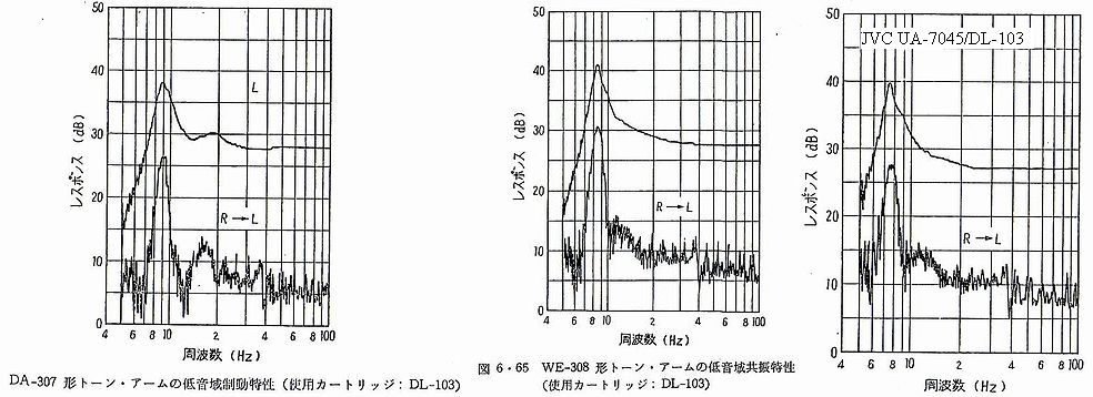
カーブが2オクターブで約半分になる(−3dB/Oct)程度で全体に低いもの(DL-103D)があります。100HzでのWcに基づく計算値よりも実測の共振点でのコンプライアンスが多めになった理由も分かりました。ADCの機械インピーダンスカーブがたまたま−6dB/Octに近くなっていたので計算値と整合したようです。軽針圧を謳ったADCが(ダンパーの劣化か)意外と重めの針圧が必要なことも分かりました。比較的古いタイプのカートリッジは機械インピーダンスも全体に高く、そのカーブも中低域で-6dB/Octを示すものが多いようです。軽針圧(VTF1.5g)のDL-103D(1977)はDL-103とは異なるダンパーを使ったようでDL-103S(1974)の後裔機です。Damper stiffness is usually different between lateral direction and vertical direction. Usually vertical stiffness of old type cartridges is higher (compliance as 1/stiffness is lower vertically). But modern cartridges claim that the stiffness to any direction is almost unchanged. Compliance=1/(2pf・[Zm] ) meaning that mechanical impedance Zm (dyne sec/cm) should have -6dB/Oct curve when compliance is perfectly constant in the stiffness controlled region (lower frequencies than 1kHz). But the mechanical impedance curve is not always so steep as theoretical -6dB/Oct. Then compliance is increasing toward lower frequencies. For example DL-103 having 5cu at 100Hz is measured to have more than 10cu (around 13cu in my estimation) around resonance frequencies. JVC book (1979) shows their measurement of actual resonances of DL-103 coupled to some arms. In my understanding the compliance of damper has non-linearity as JVC engineer in the above book (P.271) disclosed his thought: "Usual model of damper is simplified as spring and dashpot. But there is no exact equation available for representing the actual performance of rubber damper." The nature of rubber damper esp. for higher frequencies is much affected by temperature as shown in the end of my pages of frequency record. and recspecs.
The followings figures are from a Japanese book (Record Player) in 1971 written by Yamamoto
山本氏の本に載っている<各針圧下でトレースするために要求される45度方向の機械インピーダンス>の表をエクセルで再現したものが下図です。実際のレコードを調べた当時の結果(LP溝ピッチは最小40本/cm、中高音域1kH以上の最大速度振幅は約25cm/sec)に基づいています。1kHzを境に折れ曲がっているのはそこをターンオーバー点(1kHz以下は定振幅、1kHz以上は定速度の録音特性)としたから。機械インピーダンスがVTFラインより高いと針飛びしやすくなります。SP溝では中高音域の最大速度振幅がLP溝より大きくなることがSP盤にはLP盤よりも大きい針圧もしくはコンプライアンスが必要な理由だったようで、SP/LP時代のturnoverタイプのカートリッジではその問題に言及している特許文書がありますー例えばUS Patent 2,681,388 (application date March 3, 1949/patented in 1954) invented by Goldmark and SnepvangersでSPの"the maximum amplitude of excursion is approximately 0.002 inch", LPでは"the maximum amplitude of excursion of the lateral modulation is of the order of 0.0009 inch"と述べられています。
Yamamoto researched actual LP records on the market in the end of 1960s and reported that minimum pitch (40 lines/cm) and maximum recorded velocity for the range of frequency over 1kHz (peak around 25cm/s maybe in outer radius of LP and lateral ). Based on such research, the following impedance chart is simulated for determining the required VTF and the trackability of cartridge. Note that Shure's trackability chart indicated traceable maximum velocity (cm/s) with a fixed VTF while Denon indicated mechanical impedance chart(dyne sec/cm) after measuring minimum VTF and comparing to a constant velocity by division. Both have same meaning for trackability, only differ the method of expression (cm/s vs dyne sec/cm). But there remain obscurity about the kind of velocity: lateral or 45/45 direction? As far as I know: in case of indicating mechanical impedance chart, mechanical impedance for 45/45 direction is to be measured usually.
針圧とコンプライアンスの相関はほぼ以下のようになっています。 例えば1gで無難に音溝をトレースするためにはコンプライアンスは15x 10^⁻⁶cm/dyne程度必要で、コンプライアンスが5x 10^⁻⁶cm/dyne程度なら針圧は3g以上必要。 ShureはTrackabilityを一定針圧で各周波数をトレースできるそれぞれの最大速度振幅(cm/s)で表わしましたが、デンオンの機械インピーダンス表(dyne sec/cm)は一定速度振幅に換算し必要な針圧を求めることで同じくTrackabilityを表わしています。10Hz前後の共振点ではなく100Hzでの水平コンプライアンスを示す理由も共振点の計算のためではなく針圧の目安とするためだったようですーしたがってユーザには無用のスペックといえます。CBSの60年代のテストレコードSTR-100のバンド4B:100Hz水平録音0.001/0.002/0.003/0.004/0.005cmバンド5B:同内容の垂直録音で100HzにおけるコンプライアンスC=溝の振幅cm÷(980x必要針圧g)とされていました。「無難に」の程度は最大速度振幅の設定によって変わるので以下の表では約3倍(安全率)にして計算しています(100Hzの偏移0.005cmの速度振幅は3.14cm/sですので約10cm/s程度まで、即ち最大偏移0.015cmとしての計算)。MJのテストレコードでは300Hz0.005cmで針圧調整するとしていますが速度振幅は100Hz0.005cmの3倍になるので同様の意味だと思います。JIS C5503-1979(Pick-Ups)の解説には「従来から、針飛びを含めた針先コンプライアンスの普遍的な測定法がなかった。しかし、DIN45549及びIEC 98Aに対するSC-60Aなど、トラッキングアビィリティの測定法の規格化が具体化しつつあり、国内においても、日本電子機械工業会で日本レコード協会の協力を得ながらテストレコードの測定法が検討されつつある。したがって、本文では従来どおりの規定に終わったが、上記の動きを見ながら次回の改正には、さらに具体的な表現に改めたい」とありますが、カートリッジの規格は1979年版が最終版でした。以後1984年テストレコードJIS S8602の315Hzの信号溝による低域のトレース能力測定と10kHzのパルスによる高域トレース能力測定、EIAJ CP-310-8/33の20Hz-1kHz sweep信号による中低域トレース能力測定が提示されました:所定の針圧で歪なくトレースできる最大偏移(μm)を測定する。これら3段階の測定方法は現在のIEC98(1987)と同一です。特に高域トレース能力を測定する時には歪率も測定することになっています。SC-60AはIECのSound Recording部会で規格化する前にいろいろ検討協議が行われた模様。IEC98A-1972でTracking abilityの項目と試験法が示されていますが内容的に不十分(Shureなどからの異議?)だったので、1987年のIEC98では3種の信号による複雑なものになったーTracking abilityの定義は今も議論の余地を残している。
| 無難に音溝をトレースするのに必要な針圧 | 1g | 1.5g | 2g | 2.5g | 3g |
| 100Hzでのコンプライアンス(unit: x10^⁻⁶) | 15 | 10 | 7.5 | 6 | 5 |
共振点の移動と音の評価:共振点が下がると<重い低音>、上げると<軽い低音>になるとは一概に言えないようです。又、共振点が10Hzから離れると本当に問題が生じるかは他の要素を考慮にいれないと分からないようです。共振する原因となる力はテストレコードのように超低周波が記録された溝だけにあるのではなく、針と溝の摩擦やいろいろな音溝振幅により針が変移することによって実際に起こるので、共振振動数自体はさほど変わりませんがその程度(Q)は針圧やアンチスケート機構などによっても変わります。
1. Eccentric or warped record has subsonic frequencies: Off-center 0.55cycle(Lateral Wow), Warp 1.1(one-fold) - 4.4cycles(4-fold) mainly(Vertical Wow). According to Ladegaard (Fig 7. Velocity spectrum of phonograph records taken from Larry Happ & Frank Karlov, AES Preprint Number:926 1973 & JAES October 1976 under the title "Record Warps and System Playback Performance"), frequencies 0.5-7Hz caused by these warps have velocity 0.3-0.6cm/s max (which is larger than recorded velocity limit at 20Hz) while 10-18Hz has lower velocity around 0.2cm/s so that Ladegaard recommended to raise arm resonance frequency to 15-18Hz). Moreover 0.55cycle as amplitude modulation is not audible for itself or not reproducible with usual set of arm and cartridge but it is not so simple. When groove or hole is 1mm eccentric, then signal of 3.15kHz recorded laterally at radius 6cm is fluctuating between 3.1kHz〜3.2kHz by 1.8sec(one turn). Thus the rate 0.55(=once per 1.8sec) does indicate modulating frequency - such frequency modulation cannot be suppressed with usual subsonic filter.
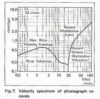
According to D.L. Taylor at JAES December 1980: Measurement of Spectral Content of Record Warps, "the horizontal variations are seen to reflect simply the center hole offset and are uncorrelated with the vertical warps. The worst case envelope for vertical warps is shown to be somewhat lower than that used by previous investigators. More importantly, the average vertical warp is seen to be an order of magnitude less than the worse case."
Our ears are said to be most sensitive to modulating frequency or wow cycle 2-4Hz so that we should avoid such wow - but what we can do for warped record ? Maybe by using stabilizer weight on record in order to flatten warped record.
2. Motor Rumble: around 25 to 30 cycles/sec with 4-pole synchronous belt-drive motor 1800rpm/60Hz or 1500rpm/50Hz (24-pole synchronous motor 5Hz? with 250-300rpm, DD motor 0.55Hz? with 100/3rpm)
3. Motor Hum: 50/60Hz and its double frequencies
4. Turntable/cabinet/plinth support resonance: around 3-10Hz? This is questionable and changing with the mass of turntable and supporting materials: Fr=(1/2pi)*SQRT(K/Mp) where K=stiffness (N/m), Mp=Mass (Kg). With conversion of above formula in SI to gravity system unit (stiffness gf/cm and Weight gram), then Fr=(1/2pi)*SQRT(980K/Mp). Being stiffness = 1/compliance, this formula is just same as that for arm-cartridge resonance. Is this vertical resonance and affecting vertical mode of arm/cart resonance only?
5. Lowest music frequency is 16Hz pipe organ. Dr. Olson said "Under very favorable conditions most individuals can obtain tonal characteristics as low as 12 cycles" (Music, Physics and Engineering: Chapter 7.4 Psychological Characteristics of Music)
These frequencies are actually differing each other - phase/vertical/lateral modes of mechanical vibrations are uncertain or unspecified usually. In USP4275888(1981) by Shure I find an interesting passage: "Although typical sources of vibrations at the resonance frequency, such as floor vibrations and record warps, have a predominantly vertical component, it has been discovered that they also have a substantial horizontal component. Some of the impact energy from a warp or a floor vibration may also be translated into lateral vibrations by passing through the tone arm suspension system".
To avoid overlapping these frequencies, 8-12Hz (resonance frequency between arm mass and cartridge compliance) is estimated as reasonable, in other words, any resonance frequency under 20Hz is possible if other factors are not affecting each other in actual product - to my regret I don't know such perfect product both on soft and hard side.
IMHO: Ladegaad in his document [Audible Effects of Mechanical Resonances in Turntables] does not refer explicitly to Psychological Characteristics of Human Ears. High or low - which is more audible? What I am inspired by Ladegaard papers is that resonance of arm/cartridge is most important factor in connection with many other resonances which affect sound.
Subsonic noise filter (HPF) or IEC suggestion about equalization (introduction of an additional time constant 7950μs/20Hz) might be made with the above consideration on arm resonance & rumble noise. -3dB difference at 20Hz (-7db at 10Hz) between recording and reproduction results from additional time constant 7950µs(20Hz) recommended by IEC60098(clause 10.2.1) year 1987.
The following equation is taken from a pamphlet attached to
MJ test record:
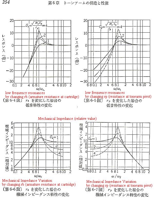
Resonance Q=2pi*ft*mt/(rb+rp)=(1/(rb+rp))*mt/SQRT(mt*C)=(1/(rb+rp))*SQRT(mt)/SQRT(C)
where rb is armature resistance at cartridge, rp is resistance at arm pivot.
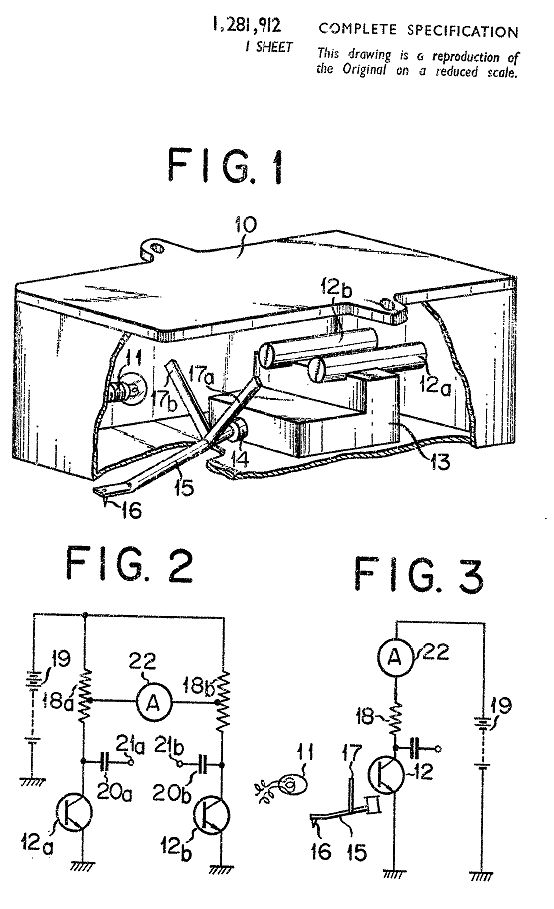
The following table is based on the above equation. Note that ft x Q becomes a constant irrespective of additional weight if combination of arm+cartridge is unchanged. This is natural result from equation ft x Q=(1/(2pi*SQRT(mt*C)))x(1/(rb+rp))*SQRT(mt)/SQRT(C)=(1/(rb+rp))*(1/2pi)/C. Note on damping factors (rb&rp): what is the relation between rb (armature resistance) and rp (resistance around arm pivot)? Yamamoto in his book (1971) explained as follows: "There are two ways of controlling the arm resonance at low frequency, that is, by equivalent resistances shown in Fig 3-13: one is armature resistance (rb) and another is resistance at arm pivot (rp). Fig 6-4, 6-5, 6-6, 6-7 shows the cases by controlling arm resonance by each factor independently. In case (Fig 6-4&6-6) of control by rb, the mechanical impedance for mid frequency increases. In case (Fig.6-5&6-7) of control by rp, the mechanical impedance for lowest frequency increases. In order to trace the record with light VTF, the mechanical impedance must be low enough for full range. Hence rb is set so as to make the high frequency flat and mechanical impedance matching. Arm resonance shall be controlled mainly by rp. But if rp is made too large, then the impedance at lowest frequency will be increased so that heavier VTF is required to trace on the warped or off-centered record."
| The effect of additional weight on shell/cartridge | mt (g) | ft (Hz) | Q | |||
| The Relation among mt, ft & Q | when | 10 | 10.06584 | 2.108185 | ||
| Compliance= | between 5-50 | 25 | *10^(-6)cm/dyne | 15 | 8.218726 | 2.581989 |
| rb+rp= | between 100-1000 | 300 | 25 | 6.366198 | 3.333333 | |
| IMO: Any imaginable improvement in sound by additional weight on shell might be applicable for high resistance for rb+rp such as heavy damped arm + low compliance cartridge only. | 35 | 5.380419 | 3.944053 | |||
| 45 | 4.745084 | 4.472136 | ||||
| Q (resonance amplitude) rate increases as resonance frequency shifts lower. | ||||||
非直線・非対称なコンプライアンスの問題:Grado氏は晩年にリニアトラッキング・アームの特許を日本に申請していました(特許公開S55-42399)ーその発明内容(針先を溝以外の余計な力から開放する工夫*下注参照)は疑問ですが針先に掛かる力を分析しているところに興味を惹かれました。針圧により縦方向にダンパーが圧縮するので、実際のカートリッジのコンプライアンスは縦方向で少なく、横方向で大きくなることが多い。それを補正するために、以下のように異形(デベソ)のダンパー(Denon
DL-7)が用いられることがあります。ダンパーについては他にもいろいろな工夫が試みられています:armaureの前後に配置するdouble
dampers(Denon/Ortofonの製品の一部で実現)、ハイコンプライアンスを維持するためダンパーの硬さを中心が硬く外周で軟らかくする工夫(2重ドーナツJP57018006やドーム状ダンパーJP57008903)、周辺温度変化により高域特性が変わるのを防ぐためダンパーの材質を従来のブチルゴムにシリコンゴムを混入する工夫(テクニクスのTTDD=US4232869や日本コロムビアのJP56094503)等等。
*注:針先を溝以外の余計な力から開放することは興味深い問題を提示しています。ダンパーのコンプライアンス(=1/Stiffness)は小さすぎるとそれ自体が運動ロスになるので或る程度大きいことが望まれます。従ってコンプライアンスは5cu〜50cuの範囲に限定されてきた背景があります。LP時代カートリッジを含めたアームの実効質量も最低でリニアトラックの場合9g前後、最高で50g前後になります。アームとカートリッジの組み合わせは低域共振周波数が通常8〜16Hzの範囲に成るように選択されます。針先とレコード盤との間の摩擦によるstylus
dragは針先・アーム支点間のテンションとなりカートリッジの実効コンプライアンスに影響を与えます。実際の製品ではコンプライアンスだけでなくアームの回転感度もしくは摩擦抵抗も縦横方向で違うものが多いのでいくら理論を展開しても実効がないことが多いと感じています。光学を用いたLaser
Turntableはstylus dragの厄介な諸問題から逃れた例だと思います。
ピックアップシステム(arm+cartridge)と針圧と針形状についての参考文献(JVC/Yamamoto/Stevenson/Bastiaans/Hunt etc.)についての記述は2021年4月削除しました。自分のお勉強用の資料でここに公開すべきものではないと判断しました。
Recently (April 2021) I omitted some referenes to Stevenson/Bastiaans/Hunt/Yamamoto/JVC and others since these references are for my reading only and nobody cares now.
![Details about mechanical impedance [zm] are explained in the technical sheet of DENON test record XG-7001](images/Mechanical%20Impedance.jpg)