Linear Trackers & Arms equipped on system players are omitted from list.
| Data
about Effective Length & Overhang are taken from Stereo Guide (SS)
and Maker's catalogues and Internet pages. There are many discrepancies among them-see also detailed NOTES(1-6). Offset angle and Null Points are only calculation so that the actual performance of arms may differ from these results. Effective length and offset angle are little variable due to following reasons. Arm side: There is no universal standard about detachable/exchageable headshell design. Mounting cartridge on the slot holes of headshell or the distance from the centre of mounting holes to arm connector on detachable headshell. Cartridge side: IEC 98 (1987) recommended the distance from the centre of mounting holes of cartridge to stylus tip should be 9.5mm +/-1mm at recommended tracking force, while JIS C5503 (1979) Phonograph pick-ups specified 10±3mm (maybe w/o tracking force). |
|||||
| MAKER | MODEL NAME | Effective LENGTH | OVERHANG | OFFSET(degree) | Null Points |
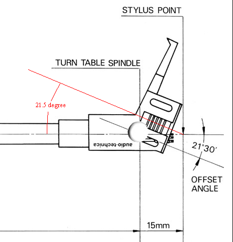
| Audio Craft | AC-30/300/3000/3300 | 237 | 15 | 21.5 (22) | 61/113 (57/120) |
| Audio Craft | AC-400/4000/4400 | 283 | 13 | 18.5 (17.5) | 60/119 (78/92) |
| Japanese manuals indicated Offset 17.5degrees for AC-4000/4400 and 22 degrees for AC-3000/3300. | |||||
| Audio-Technica | AT-1501II | 282 | 12 | 18 | 56/118 |
| Audio-Technica | AT-1501III, IV | 285 | 12 | 18 | 56/121 |
| Audio-Technica | AT-1503II | 254 | 15 | 21 | 61/121 |
| Audio-Technica | AT-1503III, IV, IIIa | 257 | 15 | 21 | 61/124 |
| Audio-Technica | AT-1100/1010/1120 | 240 | 15 | 21.5 | 60/116 |
| Audio-Technica | AT-1001/1005II/1007/1009 | 240 | 15 | 21.5 | 60/116 |
| Azden | PU-402 (SYNTEC S-220) | 220 | 15 | 22 | 62/103 |
| Azden | PU-547 & PU-550 | 237 | 15 | 21.5 | 61/113 |
| Azden | PU-549 | 244 | 15 | 21 | 64/111 |
| Denon | DA-303/305/307/309/401 | 244 | 14 | 20.5 (21) | 60/111 (56/119) |
| Denon | DA-302/304/308/1000 | 282 | 12.5 | 18 | 61/114 |
| Dynavector | DV-501/505/507 | 241 | 15 | 21.5 | 60/117 |
| Excel | ES-801 | 237 | 15 | 22 | 57/120 |
| Excel | ES-1000 & Pro S1TA | 240 | 17.25 | 22.9 | 66/121 |
| Fidelity Research | FR-12 | 230 | 14.5 | 21.4 | 60/108 |
| Fidelity Research | FR-34 | 237 | 15 | 21.5 | 61/113 |
| Fidelity Research | FR-14/FR-24/FR-54/FR-64 | 245 | 15 | 21.5 | 59/120 |
| Fidelity Research | FR-66S | 307 | 12 | 16.66 | 65/111 |
| Fidelity Research | FR-66fx | 307 | 12 | 16.82 | 63/115 |
| Grace | G-540F/640P/704/707/714/727/945 | 237 | 15 | 21 | 67/103 |
| Grace | G-565F/660P/860F/860FB/960 | 285 | 15 | 20 | 63/132 |
| Guya | STO-140 (Arm distance:237mm) | 251 | 14 | 20 as per leaflet | 63/109 |
| Ikeda | IT-407 | 307 | 12 | 16.66 | 65/111 |
| Ikeda | IT-345 & IT-245 | 245 | 15 | 21.5 | 59/120 |
| Jelco | SA-250 & SA-750D (S-shape wand) | 229 | 15 | 22 | 59/113 |
| Jelco | SA-250st (Straight wand) | 228 | 18 | 23.75 | 68/115 |
| Jelco | SA-750LB (S-shape wand) | 305 | 15 | 19 | 69/130 |
| Lustre | GST-1 | 237 | 15 | 21.6? (21) | 60/114 (67/103) |
| Lustre | GST-801 | 240 | 15 | 21.6? (21?) | 60/117 (65/107) |
| Micro | MA-202 | 237 | 15 | 21.833 (21) | 58/118 (67/103) |
| Micro | MA-303 | 222 | 15 | 22.5 (23) | 57/113 (54/120) |
| Micro | MA-701, CF-2 (static) | 237 | 15 | 21.833(21°50') | 58/118 |
| Micro | MA-505, MA-707, MAX-237, CF-1(dynamic) | 237 | 15 | 21.833(21°50') | 58/118 |
| Micro | MAX-282 & MA-505L | 282 | 12 | 17.5 | 61/109 |
| Pioneer | PA-100 | 237 | 14.5 | 21.5? | 57/117 |
| Pioneer | PA-1000 | 237 | 15 | 21.683 (21°41') | 60/116 |
| RS-Lab | Alternative alignment (underhang) | 215 | -19.6? | 0 | 93.86? |
| A-1 original setting (overhang 0 as ancient arms) | 215 | 0 | 0 | rotary shell | |
| Saec | WE-308 (circa 1971), WE-308N(1975) & WE-308SX
(1982) IMO: "Small overhang can moderate inside force." Its effective null point around 61 is based on LP's inmost recorded radius. |
240 | 5 | 12 | 39/61 |
| Saec | WE-308L(circa 1978) | 270 | 5 | 11.2 | 44/61 |
| Saec | WE-407/23(1980), WE-317S
& WE-4700(2019) English manual for WE-407/23 & WE-317S uploaded at Vinyl Engine indicated Effective Length 221, which is mistranslation of Arm Distance. Similar case as Sound ST-14. WE-407/TM for Micro (BL-99V/SX-777FV etc with armbase 1200 series). Micro Armbase 1200 series had off-center mounting hole for adjustment of arm distance/overhang. WE-407/GT (around 1986) for Yamaha GT-2000 series (Heavy Turntables around 1982). GT had different geometry. GT-2000's standard arm distance was 248mm. SAEC's tradition: they don't care much about alignment while their mechanical precision work is superb. |
The front end of
shell to arm pivot is indicated as 233mm. Then the stylus point should
be
located just under the front-end of shell. Modification after modification towards the end of analogue era is unreliable. Only interesting for a person of unusual tastes who would like something special (curiosity). I do not meddle in this kind of MESS anymore. |
12 | 18.8 (18 as per manual) |
61/89 (no null point if L233 Overhang 12 and offset 18 degrees) |
| Saec | WE-317(1982) | 248 | 13 | 19.3 | 61/103 |
| Saec | WE-506/30(1978) | 295 | 9 | 14.4 | 61/86 |
| Saec | WE-8000/ST(circa 1984) | 306 | 13 | 18 | 60.6/128.5 |
| Satin | AR-1/1M/1S | 250.5 | 15.5 | 21.5 | 62/122 |
| Sony | PUA-237 & PUA-1500S | 237 | 15 | 22.22 | 56/124 |
| Sony | PUA-286 & PUA-1500L | 286 | 13 | 18.65 | 58/125 |
| Sony | PUA-1600S | 237 | 15 | 21.5 | 61/113 |
| Sony | PUA-1600L | 286 | 14? | 18degrees? then no null point. | |
| Offset 19degrees for overhang 14mm might be far better to have null points 64/122mm. Or overhang 13mm for 18degrees might be correct to have null points 65/112mm. see note 3) | |||||
| Sony | PUA-7 | 235 | 14 | 21 | 58/111 |
| Sony | PUA-9 | 264 | 14 | 20 | 59/121 |
| Sound | ST-14 with slide base & ST-14S(standard) without slide base (same geometry as Guya STO-140). Distance 237 was wrongly quoted as effective length. Similar misleading description is repeated in Japan due to language and preference (bad practice) of indicating mounting distance for exchanging arms. For example: Catalogs from 1980s quoted 227mm for Stax short arms and 300mm for Stax long arms. | 251 (237 should be distance). When effective lateral length is 237mm, then error angle +1.5 degree/-1 degree as mentioned in leaflet cannot be obtained. | 14 | 20 | 63/109 |
| Supex | 6140 | 245 | 15 | 21.5 | 59/120 |
| Stax | UA-7/7N/7cfN/9N | 240 | 13 | 20 | 56/108 |
| Stax | UA-70/70N/90N | 312 | 12 | 17 | 60/122 |
| Technics | EPA-100/250/500 | 250 | 15 | 21 | 62/117 |
| Technics | EPA-101S & EPA-121S | 220 | 14 | 22 | 54/111 |
| Technics | EPA-101L/101T/102L/102T/121L/121T | 242 | 15 | 21.5 | 60/118 |
| Technics | EPA-99 & EPA-110 | 235 | 14 | 21 | 58/111 |
| Victor (JVC) | UA-7045 | 245 | 15 | 21.667 (21°40') | 58/123 |
| Victor (JVC) | UA-7082 | 282 | 12 | 17.5 | 61/109 |
| Yamaha | YSA-1 | 262 | 14 | 20 | 60/119 |
| Yamaha | YSA-2 pure straight arm | 228 | -20 | 0 | 97.6 |
| ADC | LMF-1 & LMF-2 | 237 | 15 | 21.6 | 60/114 |
| ADC | ALT-1 | 237 | 19 | 24.6 | 69/129 |
| Alphason | Opal/Delta/Xenon/HR100S | 229 | 18 | 24 | 66/121 |
| AudioQuest | PT-6/7/8/9 | 229 | 18 | 24 | 66/121 |
| Belcanto | Unipivot 10" | 243 | 16 | 21.75 | 66/114 |
| Belcanto | Unipivot 12" | 307 | 14 | 18.35 | 66/127 |
| Breuer | Type 5A | 228 | 20 | 25.5 | 68/128 |
| Breuer | Type 6A | 262 | 17.2 | 22 | 68/128 |
| Breuer | Type 7 & 8 | 249.44? | 18? | 23.1? | 68/128 |
| Brinkmann | 10.5 | 266.7 | 15.4 | 20.5 | 66/121 |
| Clearaudio | Unify 9" | 239.3 | 17.3 | 23 | 66/121 |
| Decca | International & Professional for transcription 12-16inches and SP record as well? | 228.6 (9inch) | 15.875 (0.625inch) | 26 | 45/155 |
| Empire | 980 & 990 | 228.6 (9inch) | 17.5? (manual indicates 5/8inch=15.875mm) | 23.8 | 64/121? (53/131 and error+/-0.65degree?) |
| EMT | 929 (it is questionable that RF229/RMA229 made by Ortofon for EMT 930 turntable had exactly same geometry as EMT 929) | 244 | 14 | 20.833 | 57/117 |
| Graham | Model 1.5t (US Patent 4686664: "for purposes of explanation only, one arm has the following dimensions: effective length 235 mm, offset angle of 23.5 degree and overhang of 17.638 mm." ) Baerwald "1" or Loefgren "2" overhang can be selectable. | 235=Baerwald | 17.6 (17.638) | 23.4 (23.5) | 66/121 (65/122) |
| 235.5=Loefgren | 18.1 (18.138) | 23.38 (23.45) | 70/117 (70/118) | ||
| Hadcock | GH228 | 228.6 | 15.75 | 23 | 57/121 |
| Hadcock | GH242 Special Edition | 243.8 | 17.8 | 23 | 69/122 |
| Helius | Orion | 252? | 16? | 21.5? | 65/119? |
| Helius | Aureus & Scorpio | 228.6 | 18 | 24 | 66/120? |
| Immedia | RPM-2 | 254 | 16 | 21.5 | 65/121 |
| Infinity | Black Widow | 237 | 15* | 21* | 67/103* |
| JML Co. | TA-3A | 229 | 18.156 | 24.102 | 66/121 |
| Keith Monks | M9BA Laboratory Arm MKIII | 228.6 | 12.7* | 19.7* | 60/94* |
| Kuzma | Stogi | 230 | 18 | 24 | 65/122 |
| Linn | Akito/Basik/Ittok/Ekos | 229 | 18 | 24 | 66/121 |
| Logic | datum S | 228 | 17.3 | 23.5 | 65/117 |
| Magnepan | Unitrac-1 | 241.3 | 17.145 | 22.8 | 66/121 |
| Manticore | Musician/Magician | 227.48 | 16.78 | 23.6 | 60/122 |
| Manticore | Magician 12inch | 304.8 | 20 | 21.967 | 79/149 |
| Mayware | Formula 4 Model PL S4/D | 224 | 15 | 22.023 | 60/108 |
| Mayware | Formula 4 MK III/IV/V | 229+/-3 | around 17 | around 23.5 | around 63.5 |
| Mission | 774 Original | 229 | 13.6 | 20.5? | 60/100? |
| Moerch | DP-6 & UP-4 | 230 | 18 | 24 | 65/122 |
| Naim | Aro | 230.5(230) | 18 | 24 | 65/122 |
| Odyssey | RP1-XG & RP1 Gold | 230 | 17.2 | 23.5 | 63.5/120 |
| Ortofon | RMG-212 & RS-212 | 228 | 16 | 22.7 | 61/114 |
| Ortofon | RMG-309 | 320 | 11 | 15.9 | 60/115 |
| Ortofon | SMG-212/SKG-212/AS-212 | 228 | 16 | 22.7 | 61/114 |
| Rega | RB250 & RB300 | 237 | 15 | 21.63 | 60/115 |
| Roksan | Artemiz/Tabriz | 240 | 17.5 | 22.9 | 68/118 |
| Schroder | Model 2 and Model DPS | 239.3 | 17.3 | 23 | 66/121 |
| SME | 3009 Series II improved with non-detachable shell and imp/S2 with detachable shell: (early=Serial Number less than 439606). Don't mix up previous Series II with imp/S2. See pdf arranged by SME for the identification of specific models IMO: S2 was named after the lightweight shell type S-2. | 231.2 | 15.86 | 22.6 | 60/117 |
| SME | 3009 II imp & imp/S2: (later=S/N 439606 or above) | 231.2 | 17.95 | 23.84 | 66/121 |
| SME | 3009III &3009IIIS (original/smaller shell) | 229 | 16 | 22.8 | 60/117 |
| SME | 3009III &3009IIIS with modified wand (larger shell) | 233.2 | 17.8 | 23.62 | 66/121 |
| SME | 3009R | 233.2 | 17.8 | 23.62 | 66/121 |
| SME | 3010R | 239.3 | 17.3 | 22.985 | 66/121 |
| SME | 3012R | 308.8 | 13.2 | 17.615 | 66/121 |
| SME | V/IV | 233.15 | 17.8 | 23.635 | 66/121 |
| SME | 309 | 232.32 | 16.97 | 23.204 | 64/119 |
| SME | 310 | 238.5 | 16.5 | 22.569 | 64/119 |
| SME | 312 | 308.19 | 12.59 | 17.278 | 64/119 |
| SME | M2-9 | 233.2 | 17.8 | 23.62 | 66/121 |
| SME | M2-10 | 239.3 | 17.3 | 22.985 | 66/121 |
| SME | M2-12 | 308.8 | 13.2 | 17.615 | 66/121 |
| SUMIKO | MMT/FT-3/FT-4 | 239 | 17.3 | 23 | 66/121 |
| Syrinx | PU-2 with minimum shell sliding on wand/PU-3 with fixed shell | 228 | 16.6 | 23.4(23)? | 60/121(64/114)? |
| Thorens | BTD-12S | 207.5 | 17.5 | 25.25 | 59/118 |
| Thorens | TP16II with TP-62 | 230 | 14.4 | 22 | 54/118 |
| Thorens | TP16III with TP-63 | 232 | 16.4 | 23 | 61/120 |
| Wheaton/Tri-Planar | Tri-Planar MKIV Ultimate | 250 | 16.5 | 22 | 65/122 |
| Wilson Benesch | ACT2& ACT 0.5 | 237 | 17.5 | 23.22 | 66/121 |
| Zeta | Zeta | 228.6 | 18 | 23.75 | 68/116 |
NOTES: There are many discrepancies in the descriptions/performance of
arms due to the following reasons.
1) Manual and model do not always coincide (manual is not enough if there
are too many modification:
history of models may be required). Some dimensions (esp. effective length) of
same model may differ between early manual and later manual even though the
product itself remains unchanged. And vice versa: same model may change
dimensions without referring to them. Often we find irregular conversion from
inch to mm in the manuals for UK/US products.
2) Incorrect worked angle: the processed tube will tend to change the angle
after a while
(someone said that Mr Breuer was watching his arms for more than 3 months).
What is the worked allowance for the offset angle of bent arm?
3) Misprint or dubious description in original documents or repetition from
secondary sources. Moreover many documents show unreliable descriptions on
error angles irrelevant to the geometry of arm. There is no standard style
of description/definition about error angles. Some adopted average error
angle divided by groove radius (for example: 0.1degree/cm). Other adopted maximum
error angle at optional radius of groove or size of record. Usually maximum
error range +/-degrees are mentioned without specifying the range of groove
radii. Who knows: the designer is nonchalant about geometry or the manual is
wrong from typo or the manufactured arm is not made in accordance with
drawing/manual etc?
4) Strained to some fixed ideas such as Baerwald/Loefgren designs. For the
honour of them, please note that so-called Stevenson/Baerwald/Loefgren designs
are not directly related with them who gave mathematical solution, method and
thought on lateral tracking angle error.
Some fixed ideas of designs will lead us to overlook the actual product as it is
produced.
In case of my KMAL M9BA MK3 Serial No. 75187(fixed shell with 2 thread
holes for inch screws),
the linear offset measured is 77mm(19.7degree)
- far from 89mm(23degree) as proposed by Audio Magazine 1980 which stated O16.2
A23 NP60/118.
*Keith Monks M9BA MKIII L228.6 O12.7 A19.7 NP60/94 when linear offset is 77mm.
I suppose that the actual geometry of my arm is similar to the above simulation.
Arm Distance (Spindle Centre to Base Centre) Mounting template indicates 8.5inch
Arm Effective Length (from arm pivot to stylus): nominal 9inch
Overhang: 0.5inch as a result and also matching to my arm. There were various
headshells so that the offset angles might be differing among these shells
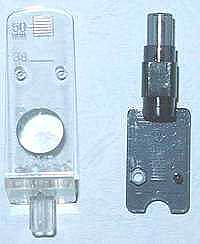
(perforated one/black thin plate shell of mine/big and robust one as seen in the
picture gallery of The Vinyl Engine). Anyway incredible offset angle 23degrees
and overhang 12.7mm were described in documents for early M9BA with robust shell
(M9BA MK I) originally produced by Audio & Design around 1967. But alignment
under such geometry shall indicate funny null points such as 41/137mm - it might
be intended for transcription disks: effective 9inch arm for 12inch records,
12inch arm for 16inch records? See also null points on Decca
International/Professional.
In case of my Infinity Black Widow with silicon oil bath and SME type
bedplate 60.5x41mm.
Audio Magazine 1980 stated L237 Distance222.641 O14.359 A21.017 NP60/110.
*But original setting template indicated distance 222mm and I think that
L237/Offset 21degrees/Overhang 15mm/Distance 222mm shall be more realistic
design figures. Then Null points 67/103mm though I could not confirm these
figures since I have not original alignment template. Anyway the linear offset
length is approx. 85mm as I measure.
5) In case of Thorens, there is much confusion due to the different exchangeable
head tube (Endrohr) types such as TP62 & TP63. Actual offset, Overhang &
Effective length shall be determined with the combination of head tube/shell and
arm tube.
6) Some old & longer arms are designed for transcription or sound
track record (16inches). I think there was standard broadcasting equipment
recommended by NAB in USA or BTS in Japan though I could not find any specific
document but suggestion in old catalogues. It is interesting to note that
the distance (from arm pivot to turntable spindle) of such arms (Audio-Technica
AT-1501II, Denon DA-302, Grace G565 & Gray 108 etc) is mostly around 270mm. Decca International/Professional arm has strange geometry in order to play back
SP, EP and LP as well. This is the meaning of "Professional" or
"Broadcasting" use.
I believe the users know the worked products better than designers or manufacturers. Hence please email to me if you find reliable data confirmed/measured by yourself (hearsay evidence is unwelcome - I've had quite enough of such kind).
Above and following calculations are based on my EXCEL sheets about Overhang adjustment on shell & comparison of arm designs which can be used at your end after saving it if you like.
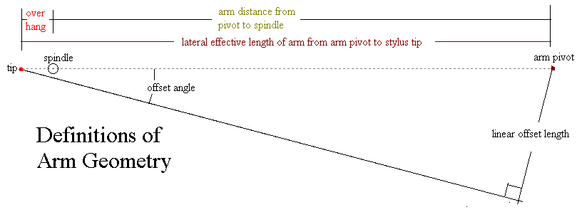
Importance of Linear Offset length rather than offset angle in arm alignment design. Effective length x SIN(offset angle)=Linear offset length. Offset angle is ASIN(Linear offset length/Effective length). (Total of null points if any)/2 equals Linear offset length. Often users discuss offset angle without questioning why some alignment tools can be applied on many different arms with certain linear offset length. Arms with same linear offset length have potential for same alignment irrespective of arm length - this is the basis of each alignment tool for two null points. Of course linear offset length can be different as per arm alignment design.
Note that linear offset or right triangle of arm
is
existing at arm pivot side (p/s/f) as well as stylus side (s/p/h). Following
drawings about alignment on bedplate show right triangle p/s/f in above drawing.
Null points b, c = Linear offset length +/-
alpha. Proper alignment is obtained by adjustment of alpha: see
Alignment Gauges.
Please note that "geometrical offset angle" is not
same as headshell offset. Headshell offset is leading us often to misunderstand the
geometrical meaning of "offset angle." See above drawing. HO=Headshell
offset angle to the straight pipe measured at the neck of shell or at
the centre of slots for mounting cartridge. A=true offset angle is
measured at stylus point against the imaginary straight line from stylus
tip to arm pivot. Hence it is not easy to measure the offset angle from
appearance. Linear offset can be measured with a carpenter's square. The
overhang adjustment on shell is not changing linear offset length as far as the
cartridge is mounted square within shell (see above right drawing) - that is
changing the effective length and the distance between two null points -
see the details on another sheet: Alignment.xls
IMO: The discernible limit on our adjustment of cartridge azimuth on shell
is: 0.5mm in length and/or 1 degree only so that I cannot believe too much in
any method of alignment. The thickness of grids on protractor must be made very thin and we must discern the difference of 0.1mm order for obtaining exact
angle alignment as seen in the following table. Man confident of having such
good sight ability might be happy enough. Now I have poor sight. [15inch monitor
screen (4:3=12x9inch) having 1024x768pixcels : one pixel size is about 0.3mm - Can
you find any dead pixel/dot on your screen?] It resembles "the problem of
mice who bell the cat" in Aesop's Fables. There is much
difference between armchair theory or calculation and actual practice.
Self-assurance or conceit prevails among
some audiophiles who would say "we did it perfectly", but nobody can
testify their performance.
| angle deviation (degree) | deviation in mm | |
| When the side of cartridge body having straight 20mm outline is aligned to grid lines on any given protractor: deviation in mm (front and rear ends of cartridge) | 0.5 | 0.17 |
| 1 | 0.35 | |
| 1.5 | 0.52 | |
| 2 | 0.70 | |
| When the direction of cantilever having whole length 8mm is aligned to grid lines: deviation in mm (front and rear ends of cantilever) | 0.5 | 0.07 |
| 1 | 0.14 | |
| 1.5 | 0.21 | |
| 2 | 0.28 | |
| In either case, there arises parallax or deviation due to one's observing point because "the whole cantilever" cannot be seen from just above or under. | ||
SME drawings for series V/IV (& 300) are also misleading or confused by indicating:
headshell offset D instead of true offset angle (=D minus included angle between grey line and wand centre line)
pivot to tip distance (A) projected laterally to horizontal line instead of straight effective line from pivot to tip
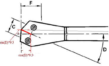
| If stylus tip is located at the centre of C, then effective length indicated by SME is incorrect. | ||||
| If we take the given dimensions as design drawing and not for the template for alignment, | ||||
| then what should be calculated dimensions based on drawing? | ||||
| True effective length straight from pivot to tip | 233.181 | mm | ||
| True offset angle when headshell offset angle D to wand is 23.635degrees | 22.699 | degrees | ||
| Linear offset length | 89.983 | mm | ||
| With given overhang F=17.8mm. | Null points: 79.381mm & | 100.584 | mm | |
| Hence if SME is truly intending Baerwald type alignments (Linear offset around 93.5mm), then we should amend the data on drawing as follows (or amend the drawing itself - it might be better for user since overhang definition F is not correct) When stylus tip has 9.5mm distance from the centre of mounting holes. | ||||
| Headshell offset angle D to make true offset angle 23.635 as a result | 24.6 | degrees | ||
| Lateral projected length A to make true effective length 233.15 | 233.116 | mm | ||
The above confusion seems to be arising from shell design. The following drawing of AT-1120 for example shows various cartridges with 10±3mm distance from the centre of mounting holes to tip can be used/aligned on this shell. This allowance 10±3mm (no mention of tracking force) should comply with JIS standard(1979) about pick-ups. IEC(1987) recommended cartridge mounting holes centre to tip: 9.5mm +/-1mm at the tracking force recommended by the manufacturer though the latter recommendation is not adopted by many cartridge makers except Audio Technica/Shure etc.
Here headshell offset angle equals actual offset angle because of the following reasons:
| 1) centre headshell line is parallel to the headshell offset line to wand in drawing |
| 2) stylus tip is located at the extension of wand centre line |
Thus there is no fixed alignment in design, make and performance (so that I believe alignment with protractor is effective as compromising method). Please also look into various alignment tools.
BTW:Most of straight arms including SME/Denon DP-7F etc are not straight actually because stylus-arm pivot-countershaft line is not exactly straight. When seeing from stylus point to arm pivot, the countershaft is biased a bit in order to counterbalance laterally the rear part of cartridge whose centre of gravity is set aside to centre line of straight arm. Thus such straight looking arms might be called just slim type of S-shaped arms. Do you like slim one (so-called straight pipe) or fatty one (S-shaped pipe)? AT-1100 sold in Japan around 1979 had interchangeable pipe system: Integral spare pipe ASP-1(straight pipe with fixed shell), Universal spare pipe ASP-11(detachable shell and S-shaped pipe as usual Japanese users prefer) and sub-counter-weight W-3 for using ASP-11. Meanwhile AT-1120 cannot change its straight arm pipe. Both AT-1100 & AT-1120 do not have lateral balance weight, whereas their stylus-arm pivot-countershaft line is exactly straight!
In 1989 Mr. Ho in Taiwan proposed "perfect dynamic balanced arm" and lateral balancing device for shell+cartridge by GB 2229848 (possible improvement for AT-1100/1120).
Though above design looks better and simple for lateral balancing, but its head weight is increased. So I admit that slim type of S-shaped arms is preferable as practical compromise.
I calculated offset angle and suitable overhang based on conventional/expedient linear offsets each specified for Stevenson and Baerwald types (these linear offsets were based on disputable/dubious recorded groove radii: inner groove radius 60.325 and outer radius 146.05mm). I assume that Stevenson in type 1B tried to compromise with smallest music radii of record formats: 7inch records for 45rpm & 33 1/3rpm (RIAA 2 1/8inch=53.975mm) and 12 inch LP records (DIN 57.5mm). His method is not differing from Baerwald essentially. It is a matter how to set inmost groove and outmost groove of actual records to be played on. Most Japanese arms seem to be designed similar to Stevenson type for EP/LP and have often constant overhang 15mm for arm length ranging from 230 to 260mm. See also my reading of Stevenson paper.
| Effective Length of Arm: L | Linear Offset 88.873mm | Linear Offset around 93.5mm | ||
| Stevenson | Overhang | Baerwald | Overhang | |
| mm | degrees | mm | degrees | mm |
| 200 | 26.4 | 18.6 | 27.9 | 21.1 |
| 205 | 25.7 | 18.1 | 27.1 | 20.5 |
| 210 | 25.0 | 17.6 | 26.4 | 19.9 |
| 215 | 24.4 | 17.2 | 25.8 | 19.4 |
| 220 | 23.8 | 16.7 | 25.1 | 19.0 |
| 225 | 23.3 | 16.3 | 24.5 | 18.5 |
| 230 | 22.7 | 16.0 | 24.0 | 18.1 |
| 235 | 22.2 | 15.6 | 23.4 | 17.6 |
| 240 | 21.7 | 15.2 | 22.9 | 17.2 |
| 245 | 21.3 | 14.9 | 22.4 | 16.9 |
| 250 | 20.8 | 14.6 | 22.0 | 16.5 |
| 255 | 20.4 | 14.3 | 21.5 | 16.2 |
| 260 | 20.0 | 14.0 | 21.1 | 15.8 |
| 265 | 19.6 | 13.7 | 20.6 | 15.5 |
| 270 | 19.2 | 13.5 | 20.2 | 15.2 |
| 275 | 18.9 | 13.2 | 19.9 | 14.9 |
| 280 | 18.5 | 12.9 | 19.5 | 14.6 |
| 285 | 18.2 | 12.7 | 19.1 | 14.4 |
| 290 | 17.8 | 12.5 | 18.8 | 14.1 |
| 295 | 17.5 | 12.3 | 18.5 | 13.8 |
| 300 | 17.2 | 12.0 | 18.1 | 13.6 |
| 305 | 16.9 | 11.8 | 17.8 | 13.4 |
| 310 | 16.7 | 11.6 | 17.5 | 13.1 |
| 315 | 16.4 | 11.5 | 17.3 | 12.9 |
| 320 | 16.1 | 11.3 | 17.0 | 12.7 |
Generally for the Japanese arms, the overhang is instructed while the place of Null points is often neglected. "Japanese record-philes" have usually several cartridges ready to use equipped on head shells (there was an accessory named "cartridge keeper or headshell stand") and are exchanging the cartridges along with head shells so frequently to enjoy the respective reproducing sound. Hence simple adjustment method (lengthwise adjustment on shell) is enough for them. Overhang is not measured directly in many cases and usually overhang adjustment is done indirectly by measuring the stylus point on shell lengthwise from the neck of exchangeable headshell when arm is pre-mounted on record player (i.e. arm distance from arm pivot to turntable spindle is already fixed so that proper overhang is obtained by adjusting effective length of arm as designed). Example of overhang gauges distributed together with cartridges: One from Denon (stylus location adjusted to the recommended distance from shell neck: usually around 50mm), another from Audio-Technica (measuring overhang directly from spindle). By these devices "Nominal effective length together with overhang" is attained as designed.
On the other hand the method for adjusting null points and offset angle is very clumsy thing: I doubt that users can adjust their specific arms perfectly in accordance with alignment tools as designed. Moreover the distortion due to lateral tracking angle error is not so great as compared with other distortions (i.e. tracing distortions). We can calculate an expected distortion due to lateral tracking angle error, but there is no actual measuring data of this distortion respectively because this rather small distortion (less than 2%) is usually masked by other much bigger distortions (often exceeding 10%) in playing a record actually. As far as I know, any authentic measuring method of this distortion due to lateral tracking angle error is not yet established. Also read the end of my recspecs about the comparison of various distortions. Very often we discuss an expected distortion due to lateral tracking angle error while we neglect an expected distortion due to vertical tracking angle error. Maybe it is again not so big problem when we hear monaural recordings (lateral recordings) only. Also read my VTA page.
ASPECTS ON ARM DESIGNS:
There are more or less important factors than simple tracking angle error.
Tracking angle error of swing arm has been discussed for long time
(Wilson/Loefgren/Bauer/Baerwald and others) and its calculation to reduce
"expected" tracking angle error is almost established. THEIR DOCUMENTS
LOOK GREAT! Hence there are so many followers or "playing groups" for every
alignments. On the other hand "how far tracking angle error distortion is
audible or not" was not discussed clearly so far. Mr. Richard Tollerton
aka AXON published at AES convention 127 (Oct. 2009): "Digital Simulation of
Phonograph Tracking Distortion." His conclusion is that it is not audible
in usual music consisting of various tones and fluctuating amplitude. His method has been supported by some audio engineers (Axon
made test CDR and nobody can discern between original music sources and their
distorted editions to certain value). Interestingly in case of pure single tone
and its distortion, the audible threshold became lower than music. In my humble opinion: alignment
calculations are related to something scientific, but audible difference due to alignment
is not confirmed scientifically. I think every tweak is concerned with
preference (should-be or expectant bias) and not science.
One holds what one has.
Recently in Japan some
"Pure Straight Arms" [PSA] without any offset angle and with underhang (minus
value overhang) alignment appeared. In SP era PSA was rather common. Early case
of this modern revival in Japan is YAMAHA YSA-2 with underhang alignment
(limited production in 1985 as option for standard YSA-1 since arm distance is same 248mm). The comparison of measured
distortions between these arms was indicated by Yamaha. In my
understanding this is measured by tracing 45 degree sweep L channel (located at
outmost) of test record so that these 2nd harmonic distortions are combination
of lateral/vertical tracking distortions and vertical tracing distortion -
tricky a bit in rushing for their conclusion that lateral tracking error is of
no importance. The points of view of PSA supporters: 1) Tracking
angle error is not so important. Usually error null point for PSA is designed at
the centre of music band i.e., around radius 8cm from the centre spindle. 2)
Conventional overhang-and-offset alignment in swing arm has fatal demerit
because stylus cantilever is always swayed according to the fluctuating
frictional forces - the fixed offset angle as designed tends to be reduced under
actual operation by the frictional forces (so to say stretch the end of bow
without string). 3) There is such gimmick as inside force canceller or
anti-skating bias prepared for swing arm. Its design target is based on the
certain fixed coefficient of force divided from frictional force between stylus
and record groove. But the frictional forces are changing rather radically and
never constant. 4) In case of PSA, the stylus cantilever angle is not affected
laterally by the above force (tension) and the cantilever direction remains at the centre
of cartridge since stylus point, cantilever pivot and arm pivot are arranged
in a straight line as seen from above. 5) The absolute value of side forces
inside and outside at PSA is smaller (roughly half) than that (only inside
force) of offset arms when arms with same effective length are compared. I will not support any "playing
group". We need various points of view. Please note that there are various
designs at the corner of the world though one would like to think one is
always at the centre of world or playing group!
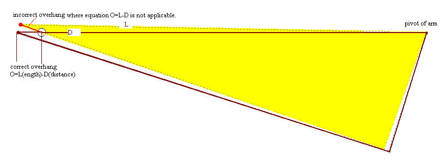
Explanations of drawing: the arc of radius L is tracking with pivoted arm while the arc of radius r is groove .
| Definition: | |||
| Effective Length | L | from arm pivot to stylus tip | |
| Arm Distance | D | from arm pivot to spindle centre | |
| Overhang | O | extension (Overhang) of arm/stylus point over spindle | |
| Groove Radius | r | groove radius from record (spindle) centre to stylus tracing point | |
| Equations: | |||
| No.1 | L=D+O | ||
| No.2 | Tracking angle An=90-c | a=ACOS ((D^2+L^2-r^2)/(2*L*D)) | |
| No.3 | COS c=(L^2+r^2-D^2)/(2*L*r) | b=ACOS ((D^2+r^2-L^2)/(2*D*r)) | |
| c=ACOS ((L^2+r^2-D^2)/(2*L*r)) | |||
| No.4 | Tracking Angle An=90-ACOS ((L^2+r^2-D^2)/(2*L*r)) | ||
| Note
on Equation No.3 (cosine theorem): C^2=A^2 +B^2 - 2*A*B *cos c
|
|||
| VARIOUS EQUATIONS of tracking angle (An) at specific groove radius. | |||
| (based on D) =Equation No.4 | 90-DEGREES(ACOS((L^2+r^2-D^2)/(2*L*r))) | ||
| (based on O) | 90-DEGREES(ACOS((2LO+r^2-O^2)/(2*L*r))) | ||
| (based on D) | DEGREES(ASIN((L^2+r^2-D^2)/(2*L*r))) | ||
| (based on O) | DEGREES(ASIN((2LO+r^2-O^2)/(2*L*r))) | ||
| (based on O) | DEGREES(ASIN(0.5r/L+(L/r)*(O/L-0.5*(O/L)^2))) | ||
| (based on O) | DEGREES(ASIN(0.5r/L+(2LO-O^2)/(2*L*r))) | ||
| These six equations are essentially identical. | |||
|
Tracking angle at specific groove radius - Fixed offset angle = Error angle at specific groove radius. |
|||